Figure 12 – HP MSA 1040 SAN Storage User Manual
Page 24
24
Installing the enclosures
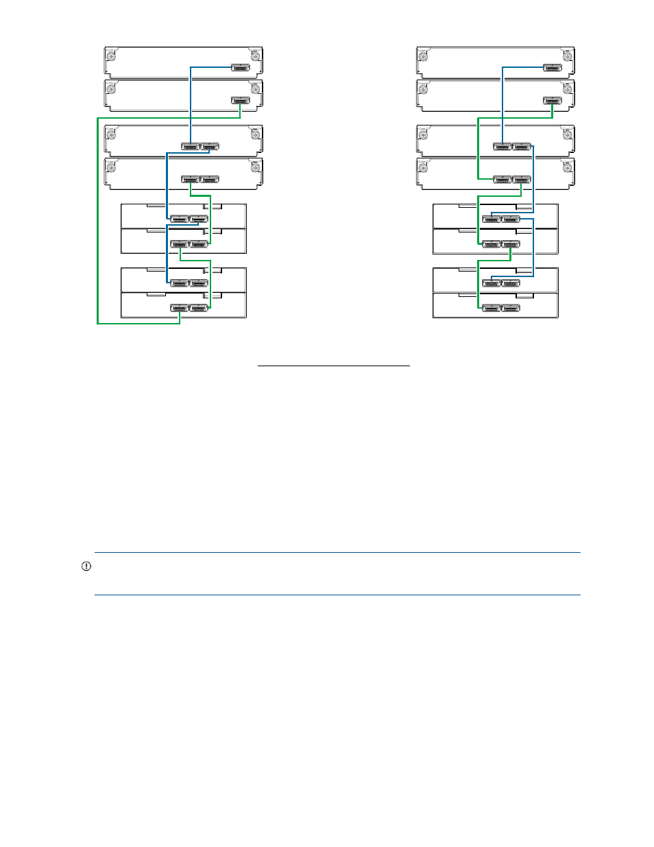
Figure 12 Cabling connections between MSA 1040 controllers and drive enclosures of mixed model type
The figure above provides sample diagrams reflecting cabling of MSA 1040 controller enclosures and
supported mixed model drive enclosures. In this example, the SFF drive enclosures follow the LFF drive
enclosures. Given that both drive enclosure models use 6 Gb SAS link-rate and SAS2.0 expanders, they
can be ordered in desired sequence within the array, following the controller enclosure.
MSA 1040 controller enclosures support up to four enclosures (including the controller enclosure) for
adding storage. Both illustrations in
show the maximum number of supported enclosures that can
be cabled together in an MSA 1040 system configuration.
IMPORTANT:
For comprehensive configuration options and associated illustrations, refer to the HP MSA
1040 Cable Configuration Guide.
1B
1A
Controller B
Controller A
3B
3A
4B
4A
P2
P2
P1
P1
2B
2A
Out
In
Out
In
Fault-tolerant cabling
1
2
2
= LFF 12-drive enclosure
1
= SFF 25-drive enclosure
2
Drive enclosure IOM face plate key:
Straight-through cabling
P2
P2
P1
P1
Controller B
Controller A
P2
P2
P1
P1
Out
In
Out
In
1
2
2
P2
P2
P1
P1
1B
1A
3B
3A
4B
4A
2B
2A