Drive enclosures, Lff drive enclosure - rear panel layout, Sff drive enclosure – HP MSA 1040 SAN Storage User Manual
Page 16: Cache, Transportable compactflash, Lff drive enclosure — rear panel layout, 6 lff 12-drive enclosure: rear panel
16
Components
IMPORTANT:
See
Connecting to the controller CLI port
for information about enabling the controller
enclosure USB Type - B CLI port for accessing the Command-line Interface via a telnet client.
Drive enclosures
Drive enclosure expansion modules attach to MSA 1040 controller modules via the mini-SAS expansion
port, allowing addition of disk drives to the system. MSA 1040 controller enclosures support adding the
6 Gb drive enclosures described below.
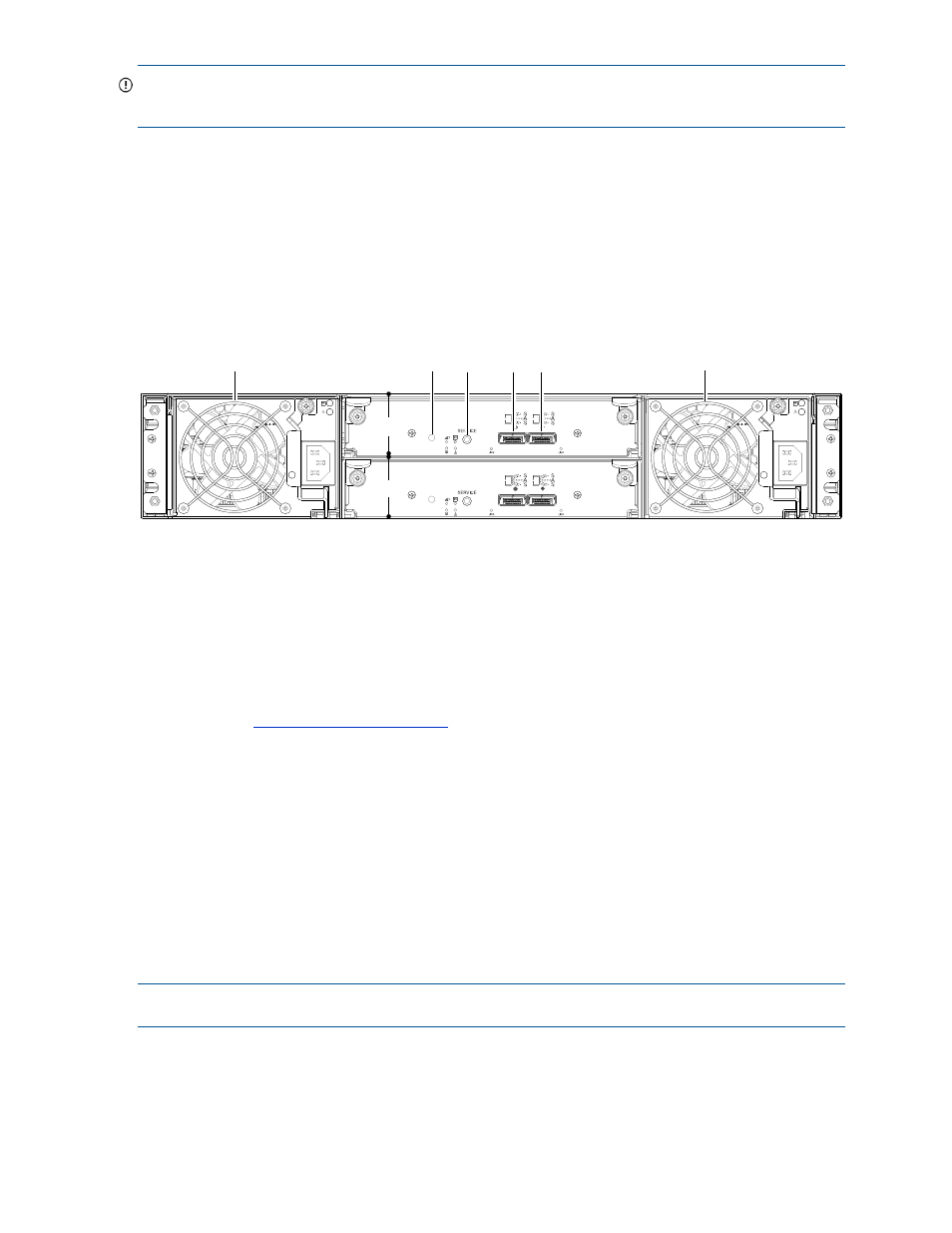
LFF drive enclosure — rear panel layout
MSA 1040 controllers support the MSA 2040 6 Gb 3.5" 12-drive enclosure shown below.
Figure 6 LFF 12-drive enclosure: rear panel
SFF drive enclosure
MSA 1040 controllers support the D2700 6 Gb drive enclosure for adding storage. For information about
this product, vi
ictorial representations of this drive enclosure are also
provided in the MSA 1040 Quick Start Instructions and MSA 1040 Cable Configuration Guide.
Cache
To enable faster data access from disk storage, the following types of caching are performed:
•
Write-back or write-through caching. The controller writes user data in the cache memory on the
module rather than directly to the drives. Later, when the storage system is either idle or aging—and
continuing to receive new I/O data—the controller writes the data to the drive array.
•
Read-ahead caching. The controller detects sequential array access, reads ahead into the next
sequence of data, and stores the data in the read-ahead cache. Then, if the next read access is for
cached data, the controller immediately loads the data into the system memory, avoiding the latency of
a disk access.
NOTE:
See HP MSA 1040 SMU Reference Guide for more information about volume cache options.
Transportable CompactFlash
During a power loss or array controller failure, data stored in cache is saved off to non-volatile memory
(CompactFlash). The data is then written to disk after the issue is corrected. To protect against writing
incomplete data to disk, the image stored on the CompactFlash is verified before committing to disk.
1
Power supplies (AC shown)
2
I/O module A
3
I/O module B
4
Disabled button (used by engineering only)
5
Service port (used by service personnel only)
6
SAS In port
7
SAS Out port
IN
OUT
IN
OUT
6Gb/s
6Gb/s
6Gb/s
6Gb/s
1
4 5
7
1
6
2
3