Chapter five - scsi bridge electronics, 9 setup display format, 10 setup overview – HP Integrity NonStop H-Series User Manual
Page 32
Chapter Five - SCSI Bridge Electronics
Tandem 5142-xSE Rackmount Tape Subsystems User Guide
2 2
When the desired tape density appears, push the mode switch to select it. The selected setting is used
until the unit is repowered or reset. The choices offered are as follows:
C0
= Compressed format
40
= Non-compressed format
FF
= Density controlled by the host software
Note:
The setting from the last change of tape density is used as the default start-up value. Density may be
changed on a tape-by-tape basis any time the tape is at BOT during normal Performance Display
operation.
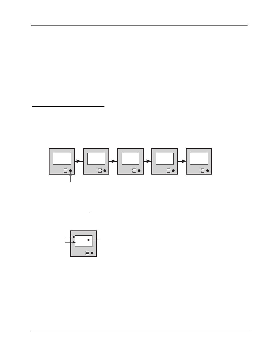
5.9
Setup Display Format
Configuration of the electronics is accomplished by using the mode switch. All values are retained in
nonvolatile memory. There are three setup menus: Setup 1 and Setup 2 contain configuration items
while Setup 3 is comprised of diagnostic and special utilities. Enter the setup menus by holding in the
mode switch while powering up the subsystem. The menu display system consists of the following
hierarchy:
Mode
Switch
*Set-Up*
Release
Button
to Start
Enter
Set-Up 1
PRESS to
Select
Enter
Set-Up 2
PRESS to
Select
Enter
Set-Up 3
PRESS to
Select
Exit
Set-Up
PRESS to
Select
Figure 25
Subsystem's setup menus
5.10
Setup Overview
Within each menu, the individual items generally take the following format on the four-line LCD:
SCSI ID:
[00]
PRESS to
Alter
Parameter
Setting
Instruction
LCD Setup Format
Figure 26
Subsystem's LCD setup format
•PARAMETER
denotes the configuration being reviewed or edited.
•SETTING
(in
SETUP 1
and
SETUP 2
) is the value that you can change.
•INSTRUCTION
describes what action should be taken if the mode switch is pressed. If the mode
switch is inactive for four seconds, the display changes. In general, the menu system is designed to show
continuously the current settings with the instruction
PRESS to Alter
, which allows the operator
the opportunity to alter the value.