Chapter five - scsi bridge electronics, 8 setting the tape density – HP Integrity NonStop H-Series User Manual
Page 31
Chapter Five - SCSI Bridge Electronics
Tandem 5142-xSE Rackmount Tape Subsystems User Guide
2 1
5.7.5
Remaining Capacity
This value is an estimate of remaining tape capacity. It is computed by multiplying the
average compression ratio by the remaining block count.
KB
,
MB
and
GB
represent
multipliers of 1024, 1024 x 1024, and 1024 x 1024 x 1024, respectively.
Read
E F
REMAIN'G
1.7GB
Figure 22
Remaining capacity readout
5.7.6
ECC/Rewrite Percentage
The number of ECC (when reading) or rewrite (when writing) occurrences, as a percentage of
the total number of read or write commands since the last rewind, display in the format
XX.X
.
In general, error rates are the highest at the beginning of a tape since this part of the tape is
written to every time the tape unloads. When this area becomes worn, tapes become unreliable.
Errors above 10.0 suggest worn tapes or the need to clean the recording heads.
Read
E F
RWr RATE
0.0%
Read
E F
ECC Rate
0.0%
Figure 23
ECC/Rewrite percentage displays
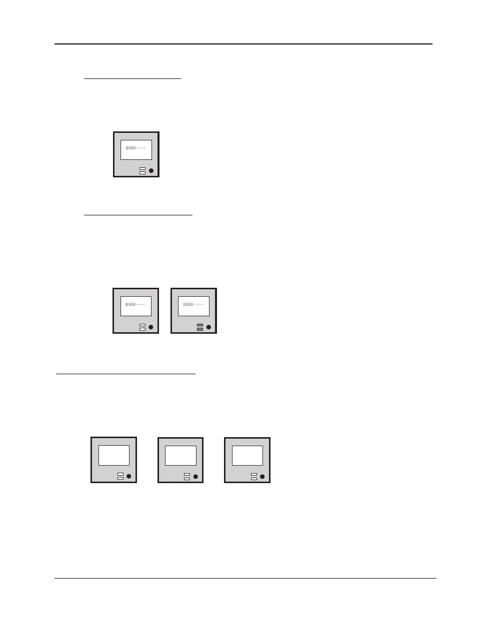
5.8
Setting the Tape Density
Tape density format may be controlled by the SCSI bridge electronics or by the host system. When the
appropriate drivers exist, the latter method is preferred and a setting of
FF
should be used. When the
unit is not busy, you can change the tape density by pressing the mode switch. Pressing the mode
switch cycles the available density settings. The options for tape density scroll on the LCD.
CO = compression on
DEN=CO
Rev L610
5170
T133BID5
40 = compression off
DEN=40
Rev L610
5170
T133BID5
Not applicable for
this application
DEN=FF
Rev L610
5170
T133BID5
Figure 24
Compression selection screens