Chapter five - scsi bridge electronics – HP Integrity NonStop H-Series User Manual
Page 30
Chapter Five - SCSI Bridge Electronics
Tandem 5142-xSE Rackmount Tape Subsystems User Guide
2 0
5.7.2
Total Data Transferred
Total data bytes read or written to/from the subsystem show with a
KB
(1024),
MB
(1024 x
1024) or
GB
(1024 x 1024 x 1024) multiplier. On the first read or write command following a
rewind, the count is set to zero.
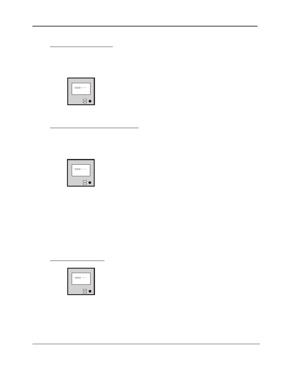
Write
E F
TOTL XFR
74MB
Figure 19
Total data transferred LCD
5.7.3
Transfer Rates in KBytes per Second
The average transfer rate between the host and the subsystem is calculated by dividing the total
data transferred by the elapsed time since the first read or write command following a rewind or
write filemark.
Write
E F
XFR RATE
425KB/s
Figure 20
Transfer rate LCD
Note:
Tape drives incorporate a data buffer to help maintain a constant data rate to the recording
heads. When this buffer is empty, 1 MB of data or more can appear to be instantly written to
the tape drive and a correspondingly high transfer rate displays. When the buffer is sufficiently
full, the recording heads are set in motion.
A substantial delay accompanies this first write-to-tape (much like the delay you experience
after pressing the play button of a VCR). This results in a drop in the transfer rate. With
continued writing to the subsystem, the tape constantly moves and the average transfer rate
approaches the quoted streaming rate.
5.7.4
Compression Ratio
Write
E F
COMPRESS
2.3:1
Figure 21
Compression ratio LCD
The average compression/decompression ratio shows as the ratio of the compressed and
uncompressed data lengths as reported by the tape drive. The ratio is always displays in the
format
X.X:X
.