E-m-xb-v1_10, Xb humidity temperature transmitter user guide – ROTRONIC XB OEM User Manual
Page 16
E-M-XB-V1_10
Rotronic AG
Bassersdorf, Switzerland
Document code
Unit
Instruction Manual
Document Type
XB Humidity Temperature Transmitter
User Guide
Document title
Page 16 of 27
© 2008; Rotronic AG E-M-XB-V1_10
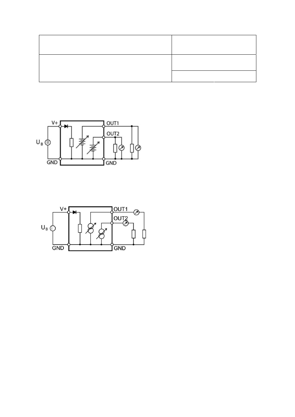
6.2.2
XB3: 3-wire transmitter
Electrical diagram for voltage outputs
The maximum permissible cable length can be
determined under consideration of the voltage drop
caused by the current flowing to the devices connected
to the unit. The voltage drop in the cable depends both
on cable resistance and on the equivalent resistance of
the devices connected in parallel to the unit. The total
resistance connected to each unit output should be at
least 1000 ohms. Cable resistance should not be more
than 1/1000 of the load resistance.
Minimum load requirements apply to the external device or circuit connected to the XB3 transmitter. These
requirements are defined in the “Operation” chapter
Electrical diagram for current outputs
The maximum permissible cable length, connecting
the unit to other devices, is determined by the total
resistance resulting from the addition of the cable
resistance and that of the devices connected in series
with the unit. This resistance should not exceed 500
ohms.