E-m-pf4-v1_00, 2 differential pressure measurement – ROTRONIC PF4 User Manual
Page 7
E-M-PF4-V1_00
Rotronic AG
Bassersdorf, Switzerland
Document Code
Unit
PF4 Differential Pressure Transmitter:
Instruction Manual
Instruction Manual
Document Type
Page 7 of 54
Document Title
© 2014; Rotronic AG
E-M-PF4-V1_00
3.2 Differential Pressure Measurement
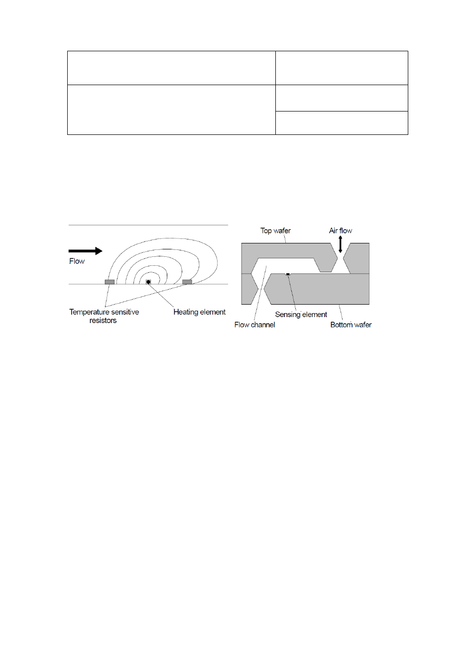
The differential pressure measurement is based on the principle of thermal mass flow. A flow limiter in a tube
generates a differential pressure. A very small quantity of gas diverted by a bypass before and after the limiter
(max. 180 µl/min) is passed over a differential pressure sensor (∆p sensor) and then returned to the main flow.
Figure 2 on the left shows the principle of this mass flow measurement.
Figure 2:
Principle of the mass flow measurement (left) and cross-section of MEMS differential pressure sensor (right)
The ∆p sensor contains a heating element and a temperature sensor each before and after the heating element.
Due to the differential-pressure dependent flow velocity in the flow passage of the ∆p sensor, the downstream
temperature sensor heats up more or less than the upstream temperature sensor. In this way it is possible to
obtain an output voltage from the ∆p sensor as potential difference between the temperature sensor output
signals that is, following careful linearization, strictly proportional to the volume flow.
The sensor used in the PF4 series is based on a 2x2 mm silicon chip (Figure 2, right). This enables production
of an extremely small and exactly reproducible flow passage with a very high pneumatic resistance, resulting in
extremely small sensor flow rates (max. 180 µl/min) and practically independent of the bypass tube lengths and
dust and moisture loads in the gas stream.
Conclusion:
The high measuring sensitivity, accuracy and long-term stability of the ROTRONIC PF4 series
make it the ideal choice for monitoring volume flows and pressures in energy-efficient and economical ventilation
and air conditioning systems.