E-m-pf4-v1_00, 5 hc2 / analog connection – ROTRONIC PF4 User Manual
Page 19
E-M-PF4-V1_00
Rotronic AG
Bassersdorf, Switzerland
Document Code
Unit
PF4 Differential Pressure Transmitter:
Instruction Manual
Instruction Manual
Document Type
Page 19 of 54
Document Title
© 2014; Rotronic AG
E-M-PF4-V1_00
4.5 HC2 / Analog Connection
The PF4 can optionally be ordered with an E2 socket. This interface and its possible uses are described below.
4.5.1
Use of HC2 Probe
The PF4 can optionally be set up for a HC2 probe. After connection of
a HC2 probe, it is possible to measure and display three parameters:
Differential
pressure
Humidity
Temperature / Calculation
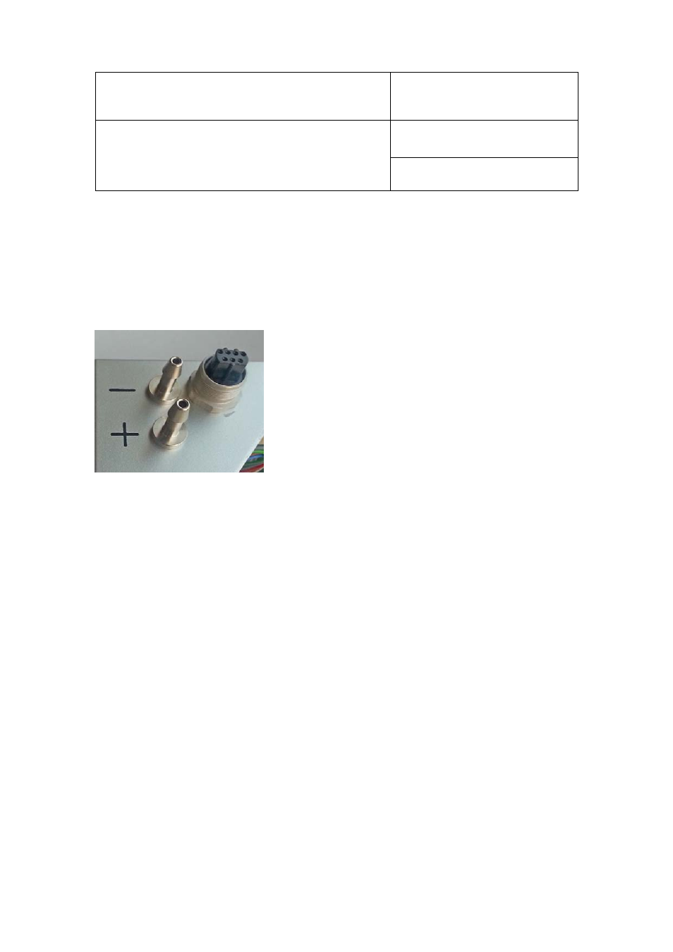
Figure 8: E2 and differential pressure connection on the bottom side
of the PF4
All HC2 probes currently available can be connected. The measured data of the HC2 probe is evaluated digitally
and shown on the display. Two of the measured values can be assigned to the analog outputs (chapter 6.2 )
and processed further. The optional Ethernet interface (chapter 6.3 ) of the PF4 can output all measured values.
4.5.2
Use of Analog Input
The device menu is used to switch between use of a HC2 probe and an analog third-party probe. The display
of the PF4 switches automatically to the units mA / mV of the analog input.
The input is reconfigured with the device menu:
MENU > Probe Information > Sensor Type
Select between the following options:
HC2
Digital HC2 probes are read out
Analog In
Analog input is used
The PF4 then asks the user to confirm the sensor change and restarts with the corresponding display
configuration.
Remark: