E-m-pf4-v1_00, 3 mounting, 4 differential pressure connection – ROTRONIC PF4 User Manual
Page 18
E-M-PF4-V1_00
Rotronic AG
Bassersdorf, Switzerland
Document Code
Unit
PF4 Differential Pressure Transmitter:
Instruction Manual
Instruction Manual
Document Type
Page 18 of 54
Document Title
© 2014; Rotronic AG
E-M-PF4-V1_00
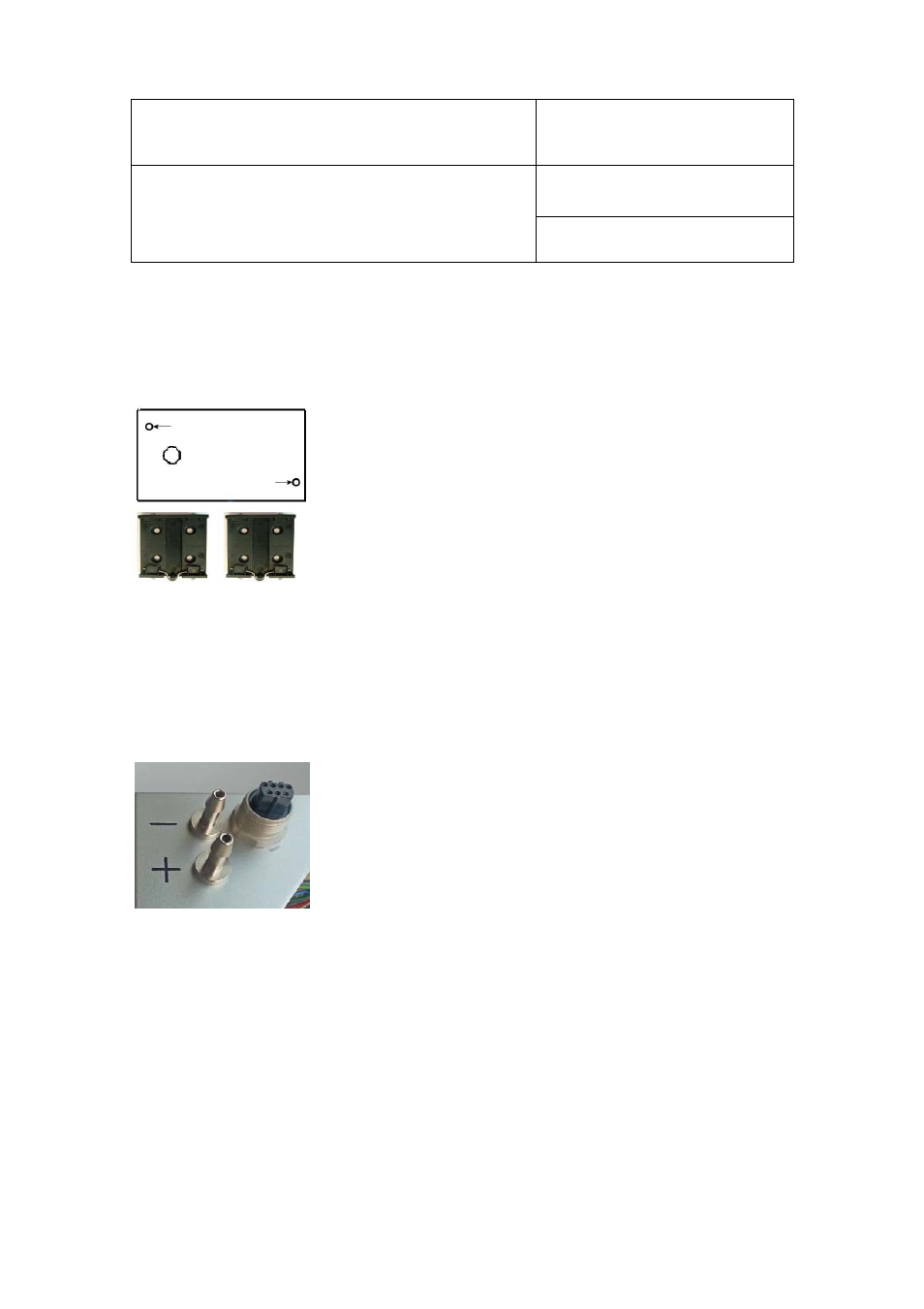
4.3 Mounting
Method 1
: The PF4 comes with two screws, two wall plugs and two rubber
washers. There are two screw depressions in the bottom part of the housing
(closed on delivery). Use the template delivered with the PF4 to drill the holes
in the wall and put in the wall plugs. Place a rubber washer under each screw
head. Put a screw in each depression and push through the bottom of the
depression.
Method 2
: The mounting kit AC5002 (not included) is needed for mounting on
a DIN top-hat rail (35 mm / 1 3/8"). The mounting kit consists of two clips, which
are fastened to the back of the housing with the screws supplied.
Figure 6: Mounting kit AC5002 and drilling points for wall mounting
4.4 Differential Pressure Connection
Tubes with an internal diameter of 4 mm
can be connected. The tubes must be fastened securely so that
they do not move or vibrate during operation. This would falsify the measurement.
Configuration of differential pressure connections:
+
: Positive pressure connection
-
: Negative pressure connection
Figure 7: Differential pressure connections and E2 socket on the bottom side of the PF4