Back panel connections, Power plug, Power switch – ROTRONIC MBW 973 User Manual
Page 26: Rs-232, External temperature, He back panel connections se, E 22. that se, External temperature o
22 Back Panel Connections
Back Panel Connections
Power Plug
The power requirements are identified on the serial number label on the back of the instrument.
Depending on the model, fuse access may also be available on or near the power plug.
Power Switch
The main power switch is mounted on the back panel near the power plug. Use the power
switch to turn the system ON and OFF.
RS-232
The RS-232 connector is used when connecting the 973 to an external computer. Use a
standard 9 pin cable to connect between the 973 and a desktop or laptop computer. The cable
is wired straight through with pins 1 through 9 of the male end wired to pins 1 through 9
respectively of the female end. The RS-232 extender cable is a common accessory item easily
obtained at most any computer accessory dealer.
See Remote Communication on page 29 for complete discussion of the RS-232 command
reference and hardware connections.
External Temperature
The External Temperature plug on the back panel is used for connection of an external
temperature probe. External temperature measurements are required if certain humidity
parameters are to be computed, such as %RH. External temperature measurements are not
required for dew or frost point measurements.
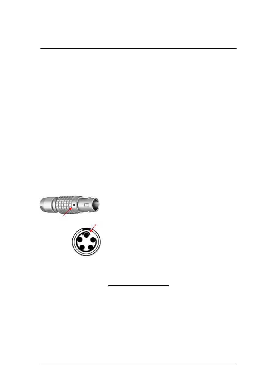
If you wish to connect your own thermometers, the 973 requires
a 5 pin connector, LEMO (www.lemo.ch) part number FGG 1B
305 CLAD 42.
When wiring the cable, note that pin numbering of the socket in
the back panel starts at the top and goes counter-clockwise (as
viewed from the rear of the unit). ). When viewing the solder
tubs of a disassembled 5-pin LEMO connector, pin 1 is usually
identified with a full or partial circle drawn around it, followed by
a line to the other pins in order.
After identifying pin 1, follow the line counter-clockwise from pin 1 to all other pins in succession.
Wire the cable according to the following:
Pin Position Signal
1 Top
Shield
2 10
o’clock
+I
3 7
o’clock +V
4 5
o’clock -V
5 2
o’clock -I
When the 5-pin LEMO connector is properly assembled, you will notice that the red dot of the
connector housing will be aligned at the top directly above pin 1.
Red Dot aligns with Pin 1