Dwyer GFC User Manual
Page 9
5
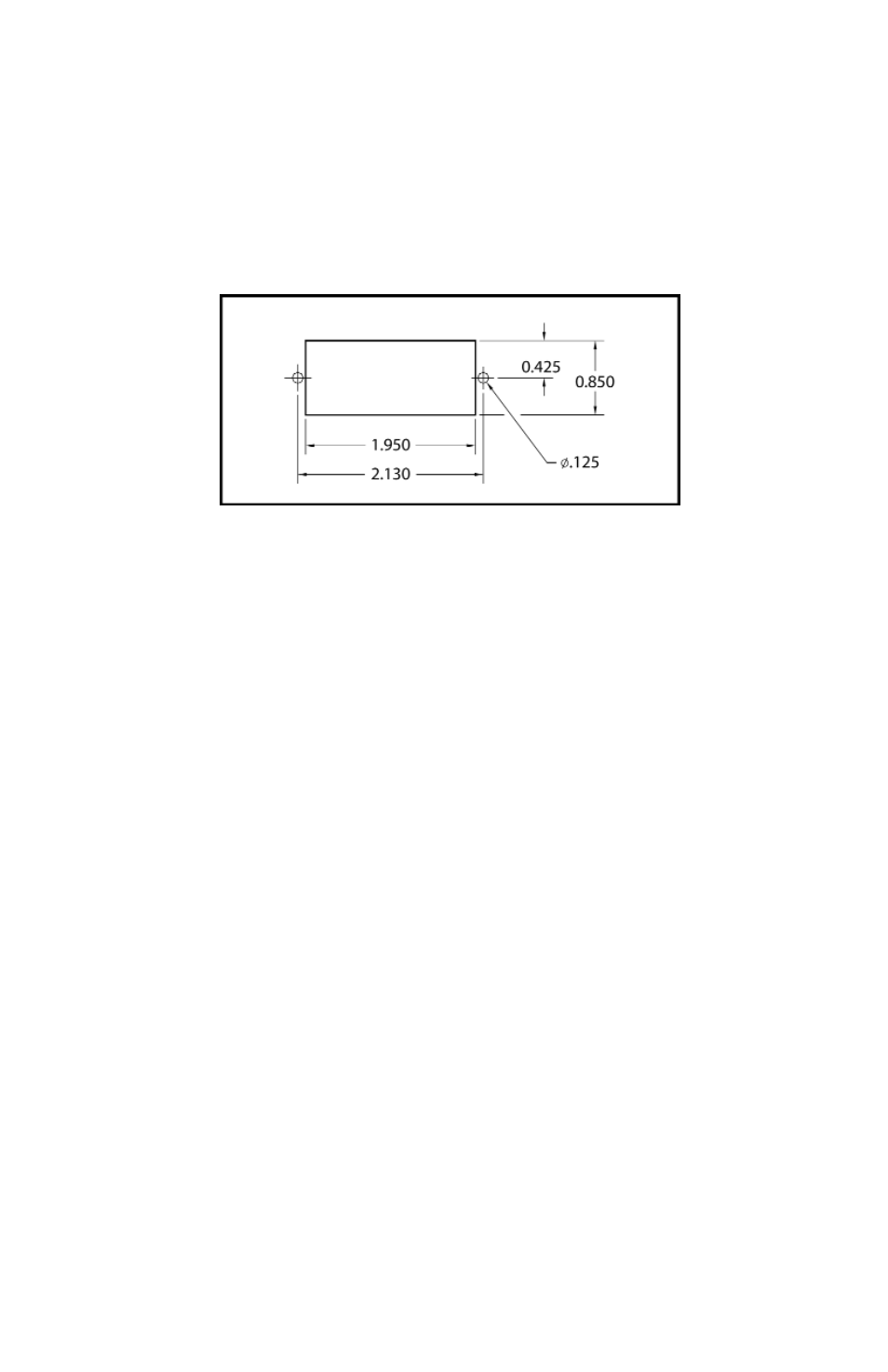
2.2.3 Panel Mounting Readouts
Another option for the GFC Mass Flow Controller is the Panel Mounting Remote
Readout.
In this configuration the LCD readout is supplied with a three foot long extension
wire, and no aluminum housing around the LCD. The LCD readout for panel
mounting includes a bezel with two plastic screws which conveniently fit into a rec-
tangular cut-out for panel mounting (see Figure 2d).
FIGURE 2-d CUTOUT DIMENSIONS FOR LCD PANEL MOUNTING.
3. PRINCIPLE OF OPERATION
The stream of gas entering the Mass Flow transducer is split by shunting a small
portion of the flow through a capillary stainless steel sensor tube. The remainder
of the gas flows through the primary flow conduit. The geometry of the primary
conduit and the sensor tube are designed to ensure laminar flow in each branch.
According to principles of fluid dynamics the flow rates of a gas in the two lami-
nar flow conduits are proportional to one another. Therefore, the flow rates meas-
ured in the sensor tube are directly proportional to the total flow through the trans-
ducer.
In order to sense the flow in the sensor tube, heat flux is introduced at two sec-
tions of the sensor tube by means of precision wound heater-sensor coils. Heat is
transferred through the thin wall of the sensor tube to the gas flowing inside. As
gas flow takes place heat is carried by the gas stream from the upstream coil to
the downstream coil windings. The resultant temperature dependent resistance
differential is detected by the electronic control circuit. The measured gradient at
the sensor windings is linearly proportional to the instantaneous rate of flow tak-
ing place.
An output signal is generated that is a function of the amount of heat carried by
the gases to indicate mass-molecular based flow rates.
GFC Mass Flow Controller models GFC-110/111/113/114 also incorporate a pro-
portionating solenoid valve and models GFC-1143/1144/1145 a motorized valve.
The closed loop control circuit of the GFC continuously compares the mass flow
output with the selected flow rate. Deviations from the setpoint are corrected by
compensating valve adjustments, thus maintaining the desired flow parameters.