Dwyer GFC User Manual
Page 15
5.4 Setpoint Reference Signal
GFC flow controllers have a built-in solenoid valve (GFC-110/111/113/114) or
motorized valve (GFC-1143/1144/1145) and allow the user to set the flow to any
desired flow rate within the range of the particular model installed. The solenoid
valve is normally closed when no power is applied.
The motorized valve can be in any position depending on the operation mode of
the GFC during disconnecting of the power. For example if the motorized valve
was left in the OPEN purge position after disconnecting power from the GFC it will
be in the OPEN position. It is the customers responsibility to provide a solution to
shut down the flow in case of a power outage. When power is applied for the
GFC-1143/1144/1145 the valve automatically closes within the first ten seconds
regardless of the set point and valve override signals.
The setpoint is controlled either locally or remotely. The setpoint input responds to
an analog 0 to 5 VDC or 4 to 20 mA reference voltage (default jumper setting is 0
to 5 VDC). This voltage is a linear representation of 0 to 100% of the full scale
mass flow rate. Response time to setpoint changes are 1 second (GFC17), 2 sec-
onds (GFC37/47) and 5 seconds (GFC-1143/1144/1145) within 2% of the final
flow over 25 to 100% of full scale.
For LOCAL flow control, use the built-in setpoint potentiometer located on the
same side as the solenoid valve of the GFC transducer. While applying flow to
the transducer, adjust the setpoint with an insulated screwdriver until the flow
reading is the same as the desired control point. [The display will only show the
actual instantaneous flow rate. There is no separate display for setpoint.]
For REMOTE control of the GFC, an analog reference signal must be supplied.
On pin 11 of the GFC transducer is a regulated and constant +5VDC output sig-
nal. This signal may be used in conjunction with a local setpoint potentiometer for
flow setting.
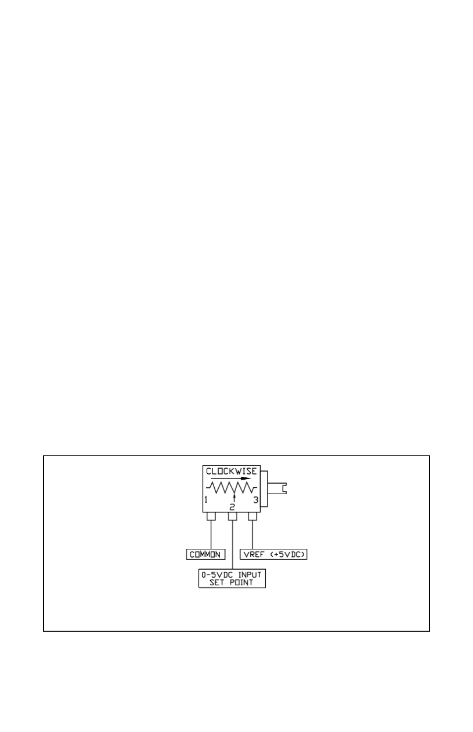
FIGURE 5-A LOCAL SETPOINT POTENTIOMETER CONNECTIONS
It is recommended that a potentiometer between 5K to 100K ohm and capable of
at least 10-turns or more for adjustment be used. Use the control potentiometer
to command the percentage of flow desired.
11