Dwyer GFC User Manual
Page 25
7.3.12 75% Flow Adjustment
Change the setpoint to 3.75 VDC to control at 75% of full scale flow. Check the
flow rate indicated against the flow calibrator. If the flow rate is not within ±0.75%
of full scale, re-adjust the setting for potentiometer [R39], until the flow output is
correct.
7.3.13 100% Flow Adjustment
Change the setpoint to 5.00 VDC to control at 100% of full scale flow. Check the
flow rate indicated against the flow calibrator. If the flow rate is not within ±0.75%
of full scale, re-adjust the setting for potentiometer [R40], until the flow output is
correct.
Repeat steps 7.3.10 to 7.3.13 at least once more.
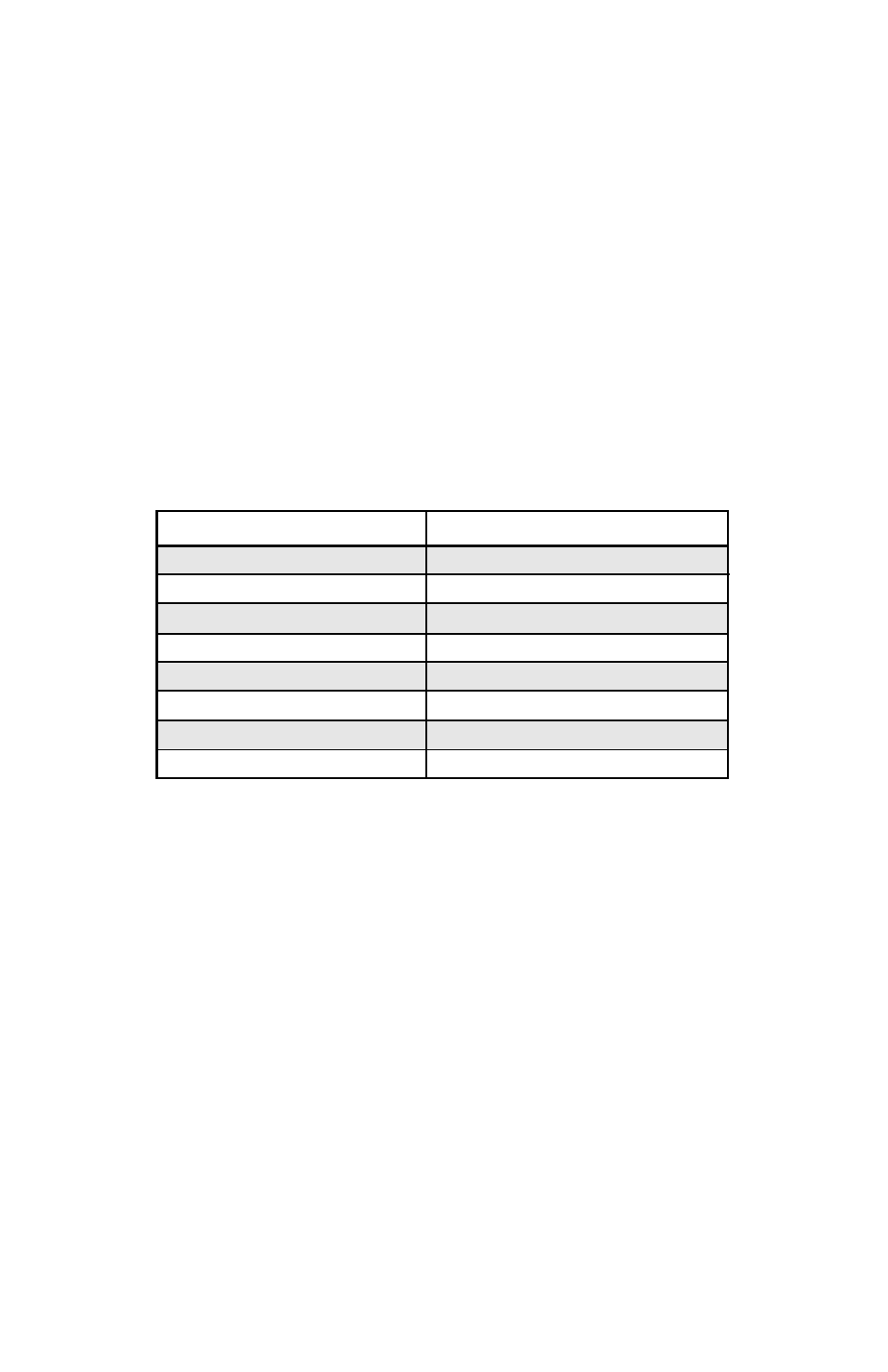
TABLE VI GFC SOLENOID VALVE ORIFICE SELECTION TABLE
7.4 LCD Display Scaling
It may be desirable to re-scale the output reading on the LCD readout supplied
with certain model GFC transducers. Re-calibration for a new flow range or dif-
ferent engineering units are two examples of when this may be necessary.
7.4.1 Access LCD Display Circuit
Carefully remove the LCD from the GFC or panel mounted surface. Remove the
aluminum housing on the side of the connection cable. Slide the LCD assembly
out of the aluminum housing.
7.4.2 Adjust Scaling
Using a digital multimeter connected to either the 0 to 5 VDC or 4 to 20 mA sig-
nal at the 15-pin "D" connector, set the flow rate on the GFC to full scale flow (5
VDC or 20mA). Maintain full scale flow, and adjust the potentiometer [R3] on the
LCD printed circuit board to desired full scale flow reading.
21
Orifice Part Number
OR.010
OR.020
OR.040
OR.055
OR.063
OR.073
OR.094
OR.125
Flow rate [ N2 ]
under 10 sccm
10 to 1000 sccm
1 to 5 slpm
5 to 10 slpm
10 to 15 slpm
15 to 20 slpm
20 to 50 slpm
50 to 100 slpm