Dwyer GFC User Manual
Page 21
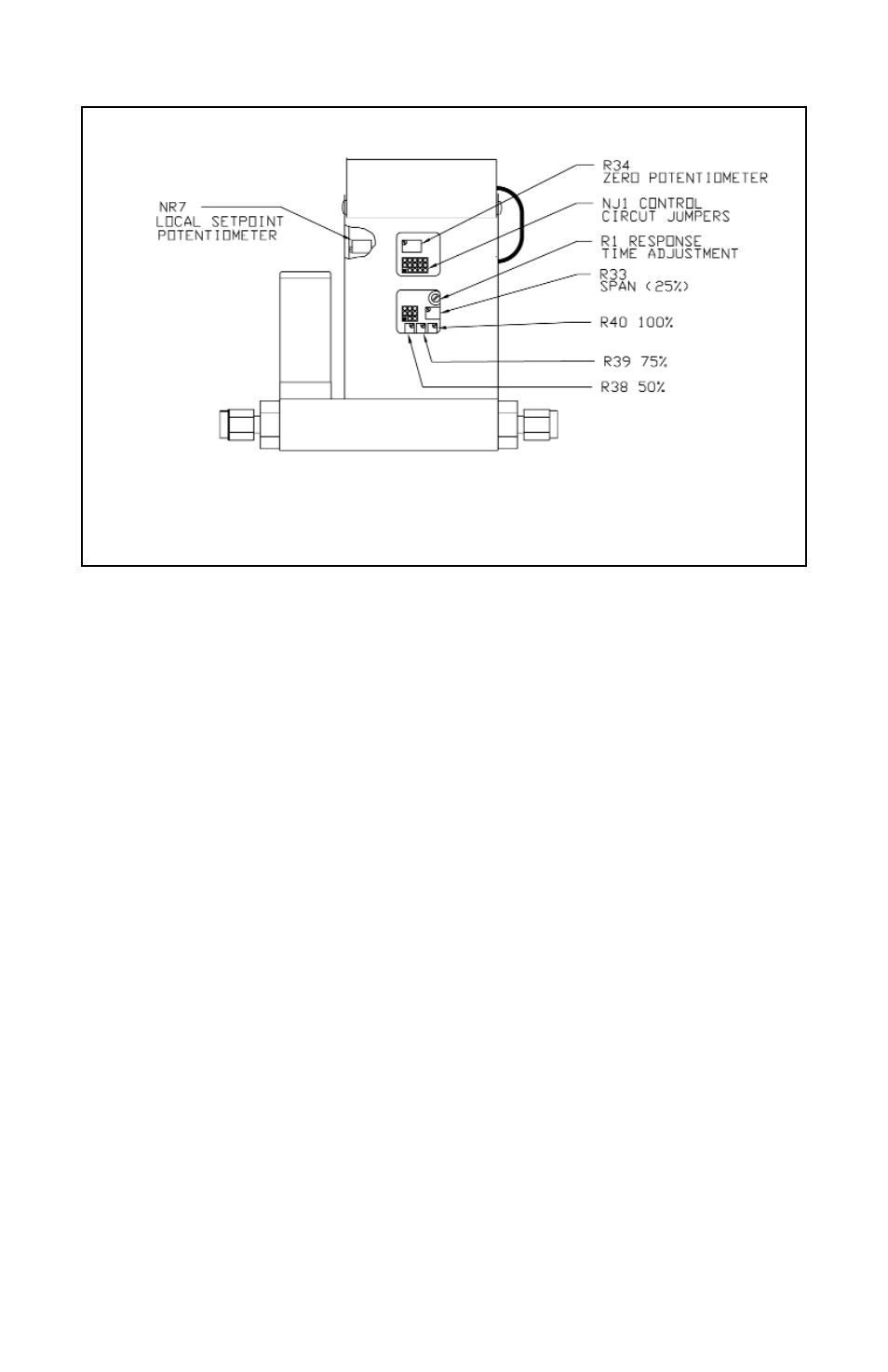
CALIBRATION POTENTIOMETER LOCATIONS ARE ILLUSTRATED IN FIGURE 9A.
FIGURE 7-a CALIBRATION POTENTIOMETER AND JUMPER LOCATIONS (BACK OF GFC)
7.2 Calibration of GFC Mass Flow Controllers
All adjustments in this section are made from the outside of the meter, there is no
need to disassemble any part of the instrument.
GFC Mass Flow Controllers may be field recalibrated/checked for the same range
they were originally factory calibrated for. When linearity adjustment is needed, or
flow range changes are being made proceed to step 7.3. Flow range changes may
require a different Restrictor Flow Element (RFE). Additionally, a different
Solenoid Valve Orifice may also be required (see Table VI). Consult your distribu-
tor or Dwyer for more information.
7.2.1 Connections and Initial Warm Up
At the 15-pin "D" connector of the GFC transducer, connect the multimeter to out-
put pins [1] and [2] for 0 to 5 VDC (or pins [9] and [14] for 4 to 20 mA) - (see Figure
2a).
When using a remote setpoint for flow control, the appropriate reference signal
should also be connected to the 15-pin "D" connector at pins [8] and [10] - (see
Figure 2a). Power up the Mass Flow Controller for at least 30 minutes prior to
commencing the calibration procedure.
17