Dwyer GFC User Manual
Page 13
5. OPERATING INSTRUCTIONS
5.1 Preparation and Warm Up
It is assumed that the Mass Flow Controller has been correctly installed and thor-
oughly leak tested as described in section (2). Make sure the flow source is OFF.
Apply power to the unit via the 15-pin "D" connector. Make certain that you are
using a power supply that is between +12 and +15 VDC with at least 800 mA cur-
rent capacity (or optionally, for models GFC110/111/113/114 only, +24 VDC 650
mA). Allow the Mass Flow Controller to warm-up for a minimum of 15 minutes.
During initial powering of the GFC transducer, the flow output signal will be indi-
cating a higher than usual output. This is indication that the GFC transducer has
not yet attained it's minimum operating temperature. This condition will automat-
ically cancel within a few minutes and the transducer should eventually zero.
If after the 15 minutes warm-up period, the display still indicates a reading of less
than ± 3.0 % of F.S., readjust the ZERO potentiometer [R34] through the access
window. Before zero adjustment it is good practice to temporarily disconnect the
gas source, to ensure that no seepage or leak occurs in to the meter.
If after the 15 minutes warm-up period, the display indicates a reading
of more than ±3.0 % of F.S., the unit has to be returned to the factory for repair.
9
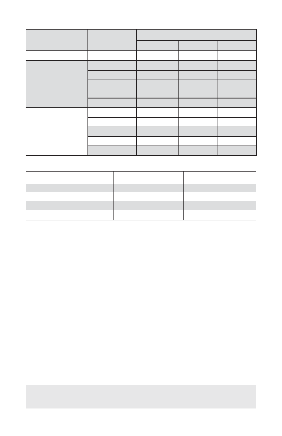
TABLE IV PRESSURE DROPS
TABLE V APPROXIMATE WEIGHTS
ƽ
1.9 lbs. (0.86 kg)
2.25 lbs. (1.02 kg)
2 lbs. (0.91 kg)
2.5 lbs. (1.13 kg)
GFC-110/ GFC-111
GFC-110/ GFC-111 Stainless
GFC-113, GFC-114
GFC-113, GFC-114 Stainless
3.4 lbs. (1.54 kg)
3.75 lbs. (1.70 kg)
3.50 lbs. (1.59 kg)
4 lbs. (1.81 kg)
model
weight
shipping weight
MODEL
FLOW RATE
[std liters/min]
MAXIMUM PRESSURE DROP
[mm H
2
O]
[psid]
[mbar]
GFC-110/GFC-111
UP to 10
720
1.06
75
GFC 113
15
2630
3.87
266
20
1360
2.00
138
30
2380
3.50
241
40
3740
5.50
379
50
5440
8.00
551
GFC 114
60
7480
11.00
758
100
12850
18.89
1302
200
7031
10.00
690
500
8437
12.00
827
1000
10547
15.00
1034