Badger Meter SRD/SRI Valve Positioners User Manual
Page 8
Features
Automatic start-up . . . . . . . . Autostart functionality
Automatic detection of mechanical stops, control
parameters and of direction of spring force. A dynamic
optimization is included in this procedure. This procedure
allows a full adaptation on optimi- zation of the positioner
to the actuator without any manual adjustments!
Options
•
Built-in independent inductive limit switches
•
Pressure Sensors for supply air pressure and output
pressure I (y1) and II (y2)
•
Additional Inputs / outputs:
•
2 binary outputs (position alarms)
•
Position feedback 4 to 20 mA + binary alarm output
•
2 binary inputs
Operation and configuration
Local . . . . . . . . . . . . . . . . . . with four keys
Display. . . . . . . . . . . . . . . . . Multi-Lingual Graphic LCD
or five LEDs
The positioner in LCD version is available with three
different menu languages:
Two menu languages are standard:
- English
- German
Freely definable third language (additional languages on
request):
- French
- Portuguese
- Spanish
- Italian
- Swedish
- etc.
The third menu language has to be selected and specified
with order.
All additional Menu languages can be downloaded into the
positioner by means of the operation- and configuration
software VALcare™. Additional language
downloads
are
available on our homepage.
Position feedback and alarms
Position feedback / valve position . . via communication
Optional
1)
. . . . . . . . . . . . . 4 to 20mA position feedback
Alarms . . . . . . . . . . . . . . . . . via communication
Optional
1)
. . . . . . . . . . . . . 1 alarm output
Position alarms . . . . . . . . . . via Kommunikation
Hi and Lo alarm
Hi/Hi and Lo/Lo alarm
Optional
1)
. . . . . . . . . . . . . 2 binary outputs
Hi and Lo alarm
Hi/Hi and Lo/Lo alarm
Independent feedback:
Limit switch (inductive) . . . . . Standard version
Security version
1) By means of additional inputs/outputs (Option Board)
Diagnosis
– local
•
Self diagnostics
•
Status- and diagnostic messages
– via VALcare™ Valve Diagnostic Software:
•
Service Management for planning and scheduling of
service intervals
•
Histograms for displaying the position- and response
history over time
•
Partial Stroke Test for the functional inspection of sa-
fety related actuators
•
Hours in operation, cycle counter and travel sum of
the actuator are determined
•
Surveillance of loop current
•
shows condition of device:
- Potentiometer
- IP Motor
- exceeding range of actuator (possible indication for
wear of plug or seat)
- remaining control deviation (possible indication for
jammed actuator, blocked valve stem or plug, not
sufficient air capacity /supply air pressure /positioning
pressure)
• if equipped with pressure sensors (optional):
• Monitoring of the stem friction
• Histograms for displaying the friction-history
over time
• surveillance of air supply and output pressure,
each with display of physical value
• Additional diagnostical possibilities in control
operation by means of external sensors (optional).
See also the VALcare™ Documentation.
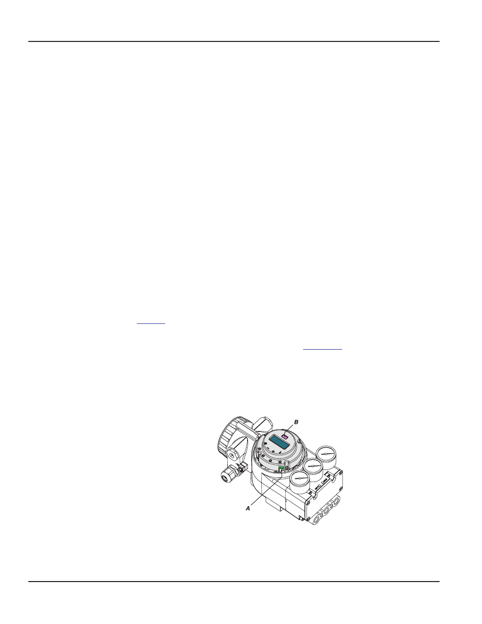
Service plug and IrCom
All basic devices are equipped with a service plug
A at the
front side. There via RS232 interface a PC with VALcare™
(DTM) can be connected via modem EDC82 (galv.
separated, not Ex).
Information about EDC82 modem see
TI EVE0102_Y
.
If the SRD is equipped with option “IrCom”
B , communication
can take place contactless via infrared with the positioner
(even with a closed cover!). A modem “IR Interface” (not
Ex) connected via RS232 interface to a PC with VALcare™
(DTM) makes communcation possible up a range of
approx. 0,5 m.
(If the notebook has an IrDa interface, this cannot be used
despite being similartechnology as IrDa instruction set has
no communication commands for positioners.)
POS-UM-00012-EN-02
Functional Specifications (Common Data for SRD960-B or -C)
Page 8
August 2014