Badger Meter SRD/SRI Valve Positioners User Manual
Page 17
1)
Operating mode min. (= Low) / max. (= high)
selectable by adjustment of switch vanes
2)
Data measured according to VDI/VDE 2177
3)
With stroke 30 mm and lever length 90 mm
4)
Operating mode normally open / normally closed selectable
by vane adjustment
5)
Approval according to UL (UL 1054) and CSA (CSA 22.2
No. 55) at 6,000 operations and T = 65 °C / 149 °F
6)
Based on EN 61058-1, at 10,000 operations and T = 85 °C
7)
General rating at 50,000 operations and T = 85 °C / 185 °F
ADDITIONAL EQUIPMENT
(continued)
Additional Inputs/Outputs built into any SRD960 -B or C
Order in Model Code: SRD960–
T, U, R, V
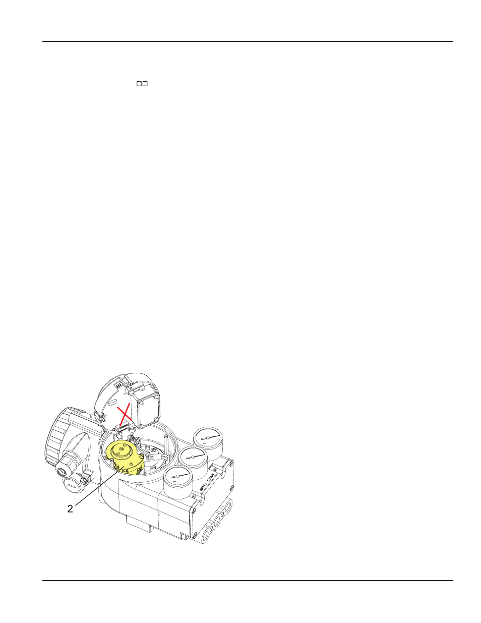
Built-in Limit Switch
[item
2
]
Inductive Limit Switch
standard version (SJ2-N) . . . . . . Code T
security version (SJ2-SN). . . . . . Code U
- in three wire technology
(SI 2-K08-AP7). . . . . . . . . . . . . Code R
Stroke / angle derivated from positioner feedback,
two-wire system
Output . . . . . . . . . . . . . . . . . 2 inductive proximity sen-
sors acc. to DIN 19 234 or NAMUR for connection to
switching amplifier with intrinsically safe control circuit
1)
Current consumption
vane clear . . . . . . . . . . . . . > 2.2 mA
vane interposed . . . . . . . . . < 1 mA
for control circuit with the following electrical values
supply voltage . . . . . . . . . . DC 8 V, R
i
approx. 1 kOhm
supply voltage range . . . . . DC 5...25 V (only with ZZZ)
residual ripple . . . . . . . . . . < 10 % p.p.
permissible
line resistance . . . . . . . . . . < 100 Ohms
Response characteristic
2) 3)
switching differential. . . . . . < 1 %
switching point repeatability < 0.2 %
Terminals for Code T, U . . . GW1 . 41+, 42–
GW2 . 53+, 54–
Terminals for Code R . . . . . . GW1 . 42
GW2 . 52
Supply 41+, 43–
Explosion protection thereto see “PHYSICAL
SPECIFICATIONS.”
Parts sets for subsequent mounting:
Code T . . . . . . . . . . . . . . . . EW 426 346 057
Code U . . . . . . . . . . . . . . . . EW 426 346 066
Code R . . . . . . . . . . . . . . . . EW 426 346 075
Built-in Limit Switch
[item
2
]
Mechanical switches
Micro Switches. . . . . . . . . . . Code V
Stroke / angle derivated from positioner feedback lever
Output . . . . . . . . . . . . . . . . . 2 mechanical switches
(Micro switches)
1) 4)
Manufacturer . . . . . . . . . . . . Saia-Burgess
Type . . . . . . . . . . . . . . . . . . V4NS-C4-AC1-UL
UL- and CSA-approved
Absolute limit values
AC
of mechanical switches built into positioner:
Umax. . . . . . . . . . . . . . . . . . 42 V AC
5)
Imax . . . . . . . . . . . . . . . . . . 0.5 A (resistive load)
5)
Imax . . . . . . . . . . . . . . . . . . 0.03 A (inductive load)
6)
Absolute limit values
DC
of mechanical switches built into positioner:
7)
Umax. . . . . . . . . . . . . . . . . . 30 V DC
Imax . . . . . . . . . . . . . . . . . . 1 A
Switching Differential:. . . . . . < 2.5 %
Terminals for SW1 . . . . . . . . 41, 42
SW2. . . . . . . . 51, 52
The circuit of the mechanical switches have to be protected
by a suitable fuse. The diameter of the protective conductor
needs to be at least 1.5 mm² / AWG 16.
Parts set for subsequent mounting
Code V . . . . . . . . . . . . . . . . EW 426 346 084
POS-UM-00012-EN-02
Additional Equipment
Page 17
August 2014