Additional equipment, Additional equipment 15 – Badger Meter SRD/SRI Valve Positioners User Manual
Page 15
ADDITIONAL EQUIPMENT
Additional Inputs / Outputs, built into any SRD960 -B or C
Order in Model Code: SRD960–
P
Order in Model Code: SRD960–
Q
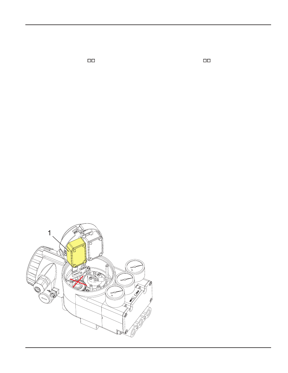
Two binary outputs
(limit signals) [item
1
]
Stroke / angle derivated from positioner feedback,
configurable
galvanically separated 2 limit signals, two-wire system,
according to DIN 19234, for external supply
supply voltage . . . . . . . . . . DC 8 to 48 V
Logic:
limit value not exceeded . . . < 1 mA
limit value exceeded . . . . . > 2.2 mA (typ. 6 mA)
device fault . . . . . . . . . . . < 50
µA
configurable as switch output:
limit value not exceeded . . . < 50
µA
limit value exceeded . . . . . > 20 mA / 20 V
> 40 mA / 10 V
(power derated)
Reference: AB1 for upper, AB2 for lower limit
Terminals for AB1 . . . . . . . . 81+, 82–
AB2
83+, 84–
Explosion protection thereto see “PHYSICAL
SPECIFICATIONS.”
Parts set for subsequent mounting:
Code P . . . . . . . . . . . . . . . . EW 426 346 021
Position feedback 4 to 20 mA [item
1
]
Stroke / angle derivated from positioner feedback,
1 output analog, galvanically separated, two-wire system
according to DIN 19234, for external supply
supply voltage. . . . . . . . . . DC 8 to 48 V
signal range . . . . . . . . . . . 3.8 to 21.5 mA
0 % and 100 % configurable
device fault . . . . . . . . . . . . < 1 mA
Terminals for AI1 . . . . . . . 31+, 32–
1 Binary output alarm, galvanically separated, two-wire
system, according to DIN 19234, for external supply
supply voltage. . . . . . . . . . DC 8 to 48 V
Logic . . . . . . . . . . . . . . . . no alarm < 1 mA
alarm > 2.2 mA
device fault < 50
µA
Terminals for AB1. . . . . . . . 81+, 82–
The binary output for Alarm will be activated in the following
cases:
- Remaining control deviation
- Circuit to I/P module is disturbed
- Circuit to potentiometer is disturbed
- Calibration error:
- no angle calibration
- no current calibration
- Autostart failed
(Pre-settings can be configured via communication)
Explosion protection thereto see “PHYSICAL
Parts set for subsequent mounting:
Code Q . . . . . . . . . . . . . . . . EW 426 346 039
SPECIFICATIONS.”
POS-UM-00012-EN-02
Additional Equipment
Page 15
August 2014