Caution, Warning, Iv. installation – Badger Meter Turbine Flow Meters (Hydraulic Fluids) User Manual
Page 9
Turbine Flow Sensor
Installation & Operating Instructions
03/12 Form No. 05-TUR-UM-00194
Page 9
IV. INSTALLATION
CAUTION
This product should be installed and serviced by technically qualified personnel trained in maintaining
industrial class flow instrumentation and processing equipment.
CAUTION
Read instructions thoroughly before installing the flow sensor. If you have any questions regarding
product installation or maintenance, call your local supplier or the factory for more information.
WARNING
Do not use male pipe threads (NPT) into SAE straight thread ports. Using male pipe threads (NPTF) with
a flow sensor possessing SAE straight thread O-ring ports will not create a proper seal and is potentially
dangerous. Pipe threads inserted into an SAE straight thread port only allow the engagement of one
or two threads. No amount of tightening or thread seal will stop the leaking or make the installation
safe. Failure to follow these instructions could result in serious personal injury or death and/or damage
to the equipment.
Installation Recommendations
The in-line flow sensor is a simple device to install. However, the following measures are recommended for
reliable, trouble-free operation:
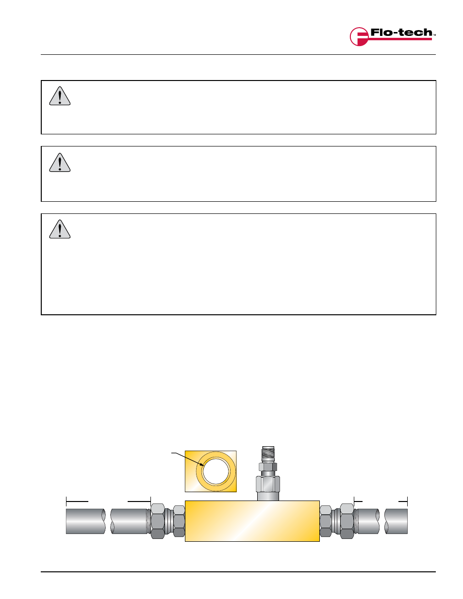
DO - Provide at least 10 port diameters of upstream straight pipe with no obstructions to the flow sensor
and at least 5 diameters of downstream pipe. The pipe should be of the same diameter as the nominal
port size.
Example:
An FSC-1000 has a one inch (25.4 mm) port. The unobstructed upstream length should be at least 10
inches (254 mm) and the downstream length should be at least 5 inches (127 mm).
FIGURE 1
Upstream and Downstream Pipe Diameters
1" PORT
(25.4 mm)
END VIEW
5 PORT DIAMETERS
5" (127 mm)
10 PORT DIAMETERS
10" (254 mm)
IN