Badger Meter Turbine Flow Meters (Hydraulic Fluids) User Manual
Page 11
Turbine Flow Sensor
Installation & Operating Instructions
03/12 Form No. 05-TUR-UM-00194
Page 11
Electrical Connections - IFC (Intelligent Frequency Converter)
The 4-20 mA output can drive auxiliary devices (resistive
loads) such as displays, recorders and computers, provided
that the voltage supplied by the power supply is adequate.
Devices must be wired in series with the F to I converter
and power supply. The voltage drop across the load(s) and
the 6 Vdc minimum needed to drive the F to I converter
determine the minimum voltage required from the power
supply.
Determine the necessary voltage required to adequately
drive the F to I converter and auxiliary device(s).
The F to I converter acts as a current controlling device.
Thus, the current output remains the same even if the power
supply voltage fluctuates or the load resistance changes.
The current varies only with respect to the flow rate from
the turbine flow sensor, as long as the voltage drop across
the F to I converter is at least 6 Vdc.
The load(s) in the circuit will generally have some electrical
resistance, 100 Ohms for this example. The 4-20 mA loop
current will produce a voltage drop across each load. The
maximum voltage drop across a load(s) will exist when
the loop current is 20 mA. The power supply must provide
enough voltage for the load(s) plus the 6 Vdc minimum
insertion loss of the F to I converter.
F to I
Converter
24 VDC
Power
Supply
4 - 20 mA
150
Ohms
100
Ohms
50
Ohms
Example 1
Sufficient Power Supply Voltage
Total Load Resistance = 300 Ohms
At 20 mA loop current, the voltage drop across the load(s)
is 6 volts:
300 Ohms × 20 mA = 6,000 mV or 6 volts
Subtract 6 volts from the 24 volt source to determine that
18 volts is available to power the F to I converter. The 18
volts is within the specified 10 to 30 volt range and is
sufficient to power the F to I converter.
F to I
Converter
24 VDC
Power
Supply
4 - 20 mA
1000
Ohms
Example 2
Insufficient Power Supply Voltage
Total Load Resistance = 1000 Ohms
At 20 mA loop current, the voltage drop across the load(s)
is 14 volts:
1000 Ohms × 20 mA = 20,000 mV or 20 volts
Subtract 20 volts from the 24 volt source to determine that
4 volts is available to power the F to I converter. The 4
volts is below the specified 10 to 30 volt range and is not
adequate to power the F to I converter. If for example, the
power supply voltage was 30 volts instead of 24 volts, the
voltage available to power the F to I converter would be 10
volts and within the specified range.
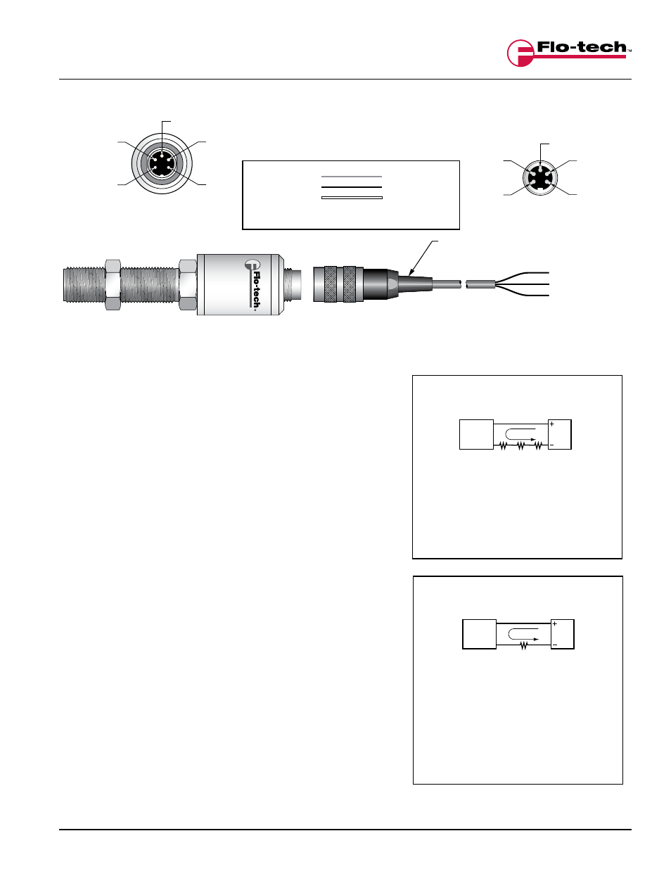
Cable
Connector
3
4
5
2
1
F to I Converter
Male Connector
3
2
1
4
5
+ 4 - 20 mA
- 4 - 20 mA
+ 4 - 20 mA (Sink)
- 4 - 20 mA (Source)
N.C.
N.C.
N.C.
PIN 3
PIN 4
PIN 5
PIN 2
PIN 1
No Connection
RED
BLACK
WHITE
(RED)
+ Loop
(WHITE) N.C.
(BLACK)
- Loop
Cable Assembly
F6557-6
6 Ft.
F6557-15 15 Ft.
FIGURE 4
IFC with 4-20 mA Output (F to I) – 5-pin Connector
FIGURE 5
Power Supply Voltage Examples