Electrical connections - standard magnetic pick-up – Badger Meter Turbine Flow Meters (Hydraulic Fluids) User Manual
Page 10
Turbine Flow Sensor
Installation & Operating Instructions
Page 10
03/12 Form No. 05-TUR-UM-00194
DO - Choose a position for the flow sensor that will not be at the lowest level in the system. Placing the
flow sensor at a higher elevation in the system will avoid collection of debris, sediment and dirt in the flow
sensor.
DO - Use a filter. All applications should be filtered to at least 40 micron.
DON’T - Locate a flow sensor directly in-line with the outlet of a pump, as pressure pulsations can react
with the turbine. Locate the sensor after another component, observing the 10 port diameter rule.
DON’T - Adjust the magnetic pick-up on the flow sensor. This is calibrated at the factory. Further adjustment
will cause a decrease in performance or damage to the sensor.
DON’T - Exceed the working temperature range of –4 °F to +300 °F (–20 °C to +150 °C). Higher
temperatures will damage the magnetic pick-up and lower temperatures will limit the rotation of the
turbine.
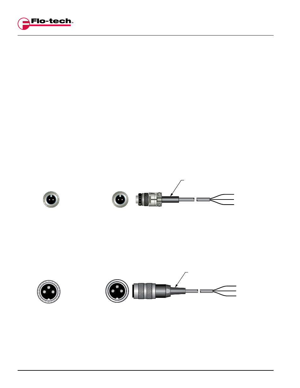
Electrical Connections - Standard Magnetic Pick-up
(BLACK)
-
(WHITE) N.C.
(RED)
+
Cable Assembly
F6234-6
6 Ft.
F6234-15 15 Ft.
Top of
F6234 Cable
3
2
1
1 - (WHITE) N.C.
2 - (BLACK) -
3 - (RED) +
Magnetic Pick-up
Male Connector
1
2
3
(BLACK)
-
(WHITE) N.C.
(RED)
+
Cable Assembly
F2832-6
6 Ft.
F2832-15 15 Ft.
A -
(RED)
+
B -
(BLACK)
-
Top of
F2832 Cable
B A
Magnetic Pick-up
Male Connector
B
A
FIGURE 2
Standard Magnetic Pick-up with Frequency Output – 2-pin Connector
FIGURE 3
Standard Magnetic Pick-up with Frequency Output – 3-pin Connector