Figure 3, Figure 4 – Badger Meter 3-A Sanitary User Manual
Page 8
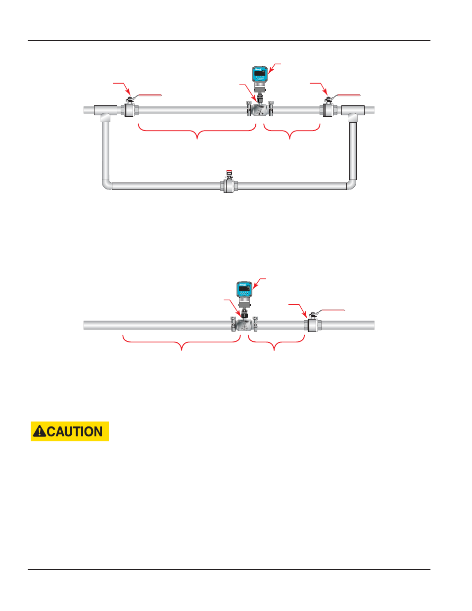
Bypass Line
5 Pipe Diameters
Minimum
10 Pipe Diameters
Minimum
Isolation
Valve
Display
FloClean Turbine
Flow Meter
Isolation
Valve
2
1
Figure 3: Installation with bypass line
This is true with any restriction in the flow line that may cause the liquid to flash If necessary, air eliminators should be
installed to ensure that the meter is not incorrectly measuring entrained air or gas
It is recommended that a minimum length, equal to ten (10) pipe diameters of straight pipe, be installed on the upstream side
and five (5) diameters on the downstream side of the flow meter Otherwise, meter accuracy may be affected Piping should
be the same size as the meter bore or threaded port size
5 Pipe Diameters
Minimum
10 Pipe Diameters
Minimum
FloClean Turbine
Flow Meter
Isolation
Valve
Display
2
1
Figure 4: Installation without a bypass line
Do not locate the flow meter or connection cable close to electric motors, transformers, sparking devices, high voltage lines,
or place connecting cable in conduit with wires furnishing power for such devices These devices can induce false signals in
the flow meter coil or cable causing the meter to read inaccurately
DAMAGE CAN BE CAUSED BY STRIKING AN EMPTY METER WITH A HIGH VELOCITY FLOW STREAM.
If problems arise with the flow meter and monitor, consult the
TROUBLESHOOTING GUIDE on page 16
If further problems
arise, consult the factory
If the internal components of the turbine flow meter are damaged, turbine meter repair kits are available Information
pertaining to the turbine meter repair kits is referenced in
Turbine Flow Meter, FloClean Sanitary Flow Meter
Page 8
November 2013