Operational startup, Dimensions/drawings, Operational startup 11 – Badger Meter 3-A Sanitary User Manual
Page 11: Dimensions/drawings 11
Operational Startup
The following steps should be followed when installing and starting the meter
MAKE SURE THAT FLUID FLOW HAS BEEN SHUT OFF AND PRESSURE IN THE LINE RELEASED BEFORE ATTEMPTING TO
INSTALL THE METER IN AN EXISTING SYSTEM.
1 After meter installation, close the isolation valves and open the bypass valve Flow liquid through the bypass valve for
sufficient time to eliminate any air or gas in the flow line
2 Open upstream isolating valve slowly to eliminate hydraulic shock while charging the meter with the liquid Open the
valve to full open
HIGH VELOCITY AIR OR GAS MAY DAMAGE THE INTERNAL COMPONENTS OF THE METER.
3 Open downstream isolating valve to permit meter to operate
4 Close the bypass valve to a full closed position
5 Adjust the downstream valve to provide the required flow rate through the meter
OTEE:
N
The downstream valve may be used as a control valve
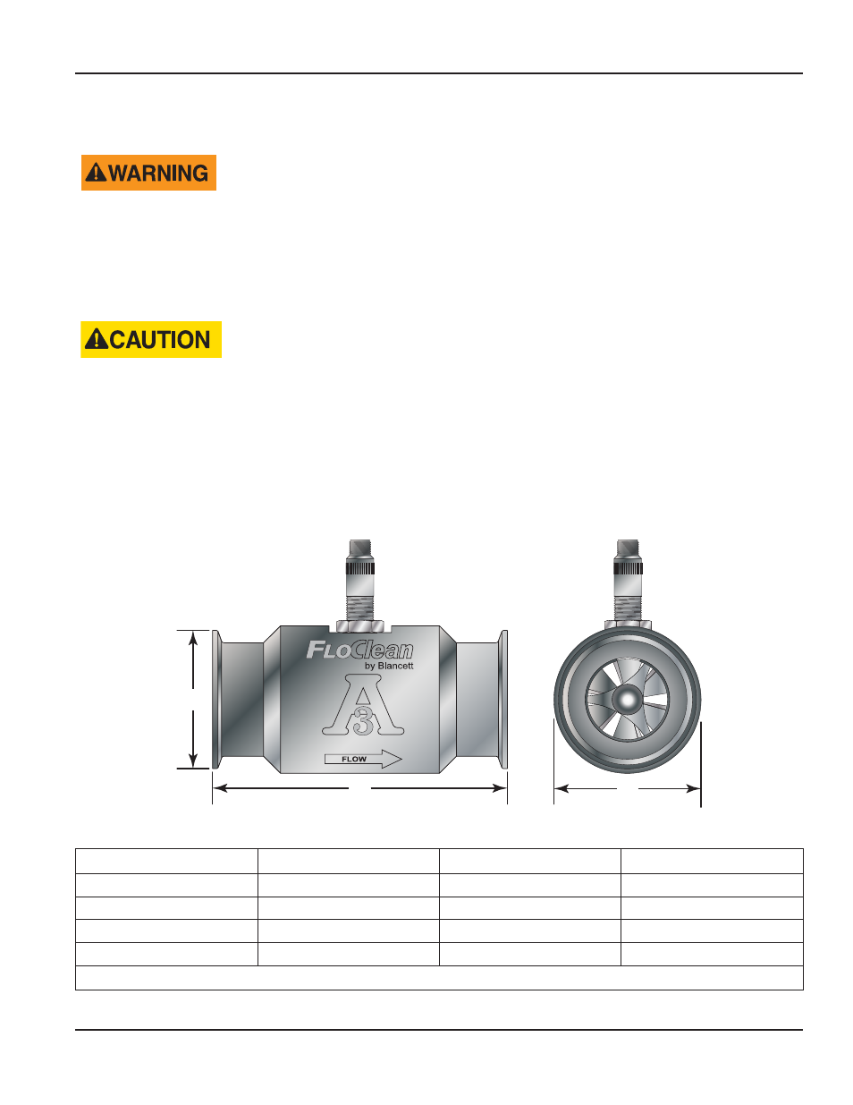
DIMENSIONS/DRAWINGS
A
B
C
Stnd. #28-04 Auth. #956
Figure 8: Dimensions
Part No.
A
B
C – Ferrule Size
B16C-0XXA-XXX
3 00 in (76 2 mm)
1 46 in (37 1 mm)
0 984 in (25 0 mm)
B16C-1XXA-XXX
4 00 in (101 6 mm)
2 00 in (50 8 mm)
1 984 in (50 4 mm)
B16C-1XXA-XXX ¹
6 25 in (158 8 mm)
2 33 in (59 2 mm)
1 984 in (50 4 mm)
B16C-2XXA-XXX
6 50 in (165 1 mm)
3 20 in (81 3 mm)
3 047 in (77 4 mm)
¹
15 0…180 0 gpm flow range only
Table 4: Dimensions
User Manual
Page 11
November 2013