Badger Meter M-Series M3000 User Manual
Page 7
7
METER/AMPLIFIER LOCATION, ORIENTATION and
APPLICATIONS
Remote Amplifi er Outdoor Location
The amplifi er can be installed and operated outdoors.
However, protection from the elements must be considered:
1. Be aware of the ambient environment and
temperature ratings for the unit -4°F to 122°F (-20°C to
50°C).
2. If an indoor location is within 100 feet (30m) of the
detector installation, consider increasing the cable length
and mounting the amplifi er indoors.
3. At a minimum, fabricate a roof or shield over and/or
around the amplifi er to protect the LCD display screen
from sunlight.
Temperature
To prevent meter damage in any environment, minimum and
maximum temperature ranges must be observed.
1. For remote amplifi er applications, the fl uid temperature
range is -4°F to 248°F (-20°C to 120°C) at a maximum
ambient temperature of 122°F (50°C) for the following
liner materials: PFA, PTFE and Halar
®
.
2. For remote amplifi er applications, the fl uid temperature
range is 32°F to 178°F (0°C to 80°C) at a maximum
ambient temperature of 122°F (50°C) for the following
liner materials: Hard rubber and soft rubber.
3. For meter mounted amplifi er applications, the fl uid
temperature range is -4°F to 212° (-20°C to 100°C) at a
maximum ambient temperature of 122°F (50°C) for the
following liner materials: PFA, PTFE and Halar.
4. For meter mounted amplifi er applications, the fl uid
temperature range is 32°F to 178°F (0°C to 80°C) at a
maximum ambient temperature of 122°F (50°C) for the
following liner materials: Hard rubber and soft rubber.
5. The ambient temperature range surrounding the amplifi er
is -4°F to 122°F (-20°C to 50°C.)
6. The ambient temperature range surrounding a remote
junction box mounted to the detector is -4°F to 248°F
(-20°C to 120°C.)
Pipelines and Fluid Flow
Pipeline and fl uid fl ow conditions that should be avoided:
1. Do not install the meter where extreme pipe vibrations
exist. If vibrations are present, secure piping before
and after the meter with appropriate pipe supports. If
vibrations can’t be restrained, consider mounting the
amplifi er remotely.
2. Avoid installing the detector close to pipeline valves,
fi ttings or impediments that can cause fl ow disturbances.
3. For detectors with PTFE liners, avoid installing the
detector on suction sides of pumps.
4. Avoid installing the detector on outlet sides of piston
or diaphragm pumps. Pulsating fl ow can affect meter
performance.
5. Avoid locations near equipment producing electrical
interference such as electric motors, transformers, variable
frequency, power cables, etc.
6. Verify both ends of the signal cables are securely
fastened.
7. Place power and signal cables in separate conduit.
8. Place the meter where there is enough access for
installation/maintenance purposes.
Meter Orientation
Mag meters can operate accurately in any pipeline
orientation and can measure volumetric fl ow in forward and
reverse directions.
NOTE: A Forward Flow direction arrow is printed on the
detector label.
Vertical Placement
Mag meters attain optimal performance when placed
vertically, with liquid fl owing upward and meter electrodes in
a closed, full pipe.
Vertical placement allows the pipe to remain completely full,
even in low fl ow, low pressure applications and it prevents
any solids build-up or sediment deposit or accumulation on
the liner and/or electrodes.
NOTE: Carefully observe the “Forward Flow” label on the
meter body and install the meter accordingly.
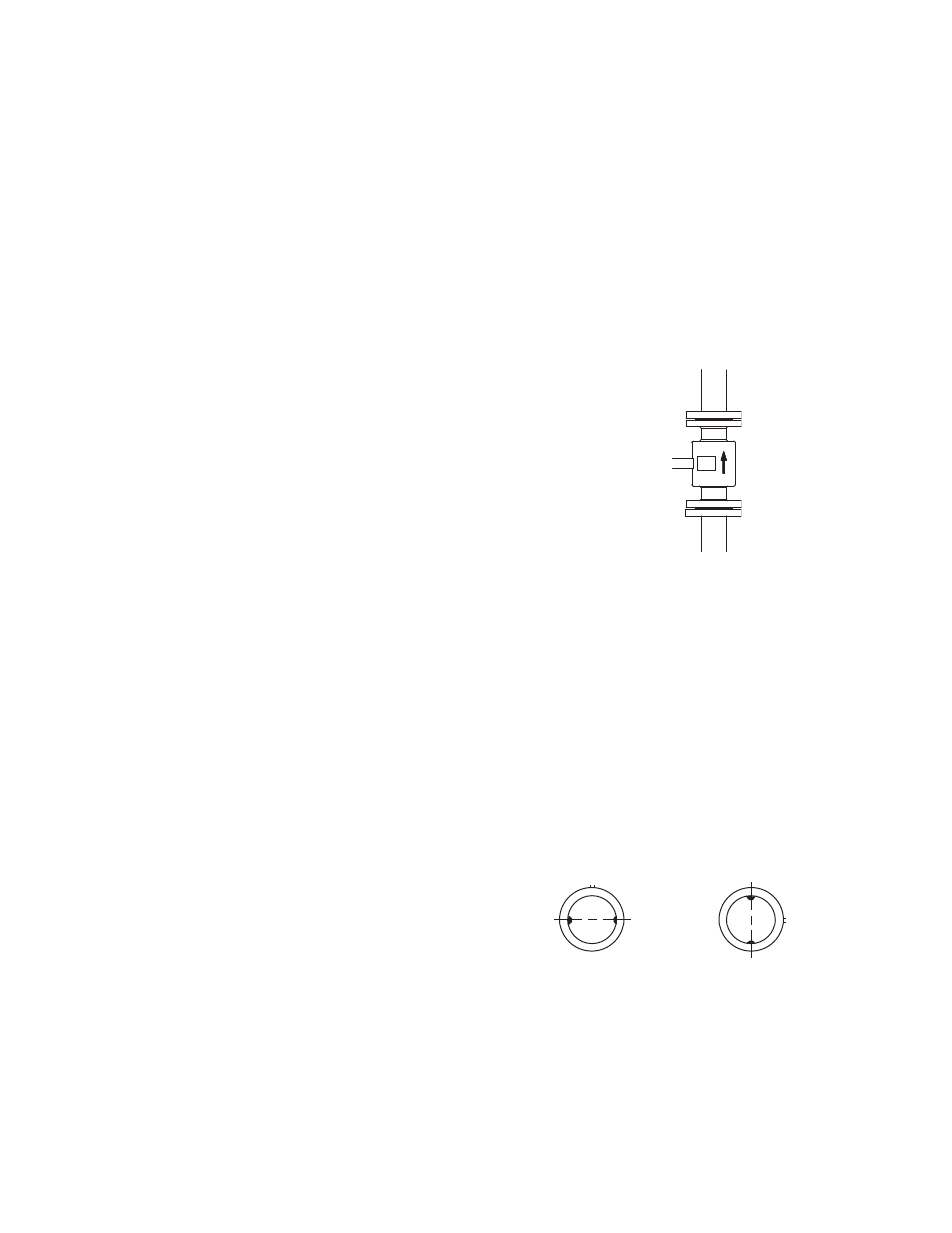
Horizontal Placement
In a horizontal piping orientation, mount the detector to
piping with the fl ow measuring electrode axis in a horizontal
plane (3 and 9 o’clock).
This arrangement prevents solids build-up or sediment
deposit or accumulation on the electrodes.
Electrode
Plane
RIGHT
Electrode
Plane
WRONG