Mount bracket to amplifier, Wiring configuration, Wiring for remote configuration – Badger Meter M-Series M5000 User Manual
Page 15: Configuring input/output (i/o)
Mount Bracket to Amplifier
1 . Align bracket-mounting holes with amplifier mounting holes .
2 . Attach bracket to amplifier with supplied screws . Torque the screws to 80 inch-pounds .
Wiring Configuration
Wiring between the detector and the M5000 amplifier comes complete from the factory . If your installation requires the use
of conduit, we recommend that you follow these steps when wiring the detector to the amplifier .
1 . Carefully remove the wires connected to the terminal blocks that run to the M5000 amplifier or to the junction box . See
the chart below for a reference of wire color to terminal connection .
2 . Run cable through the conduit while retaining the wiring of the cable to the amplifier or the junction box, as supplied .
3 . Complete conduit assembly on both ends and rewire the cable as it was previously wired .
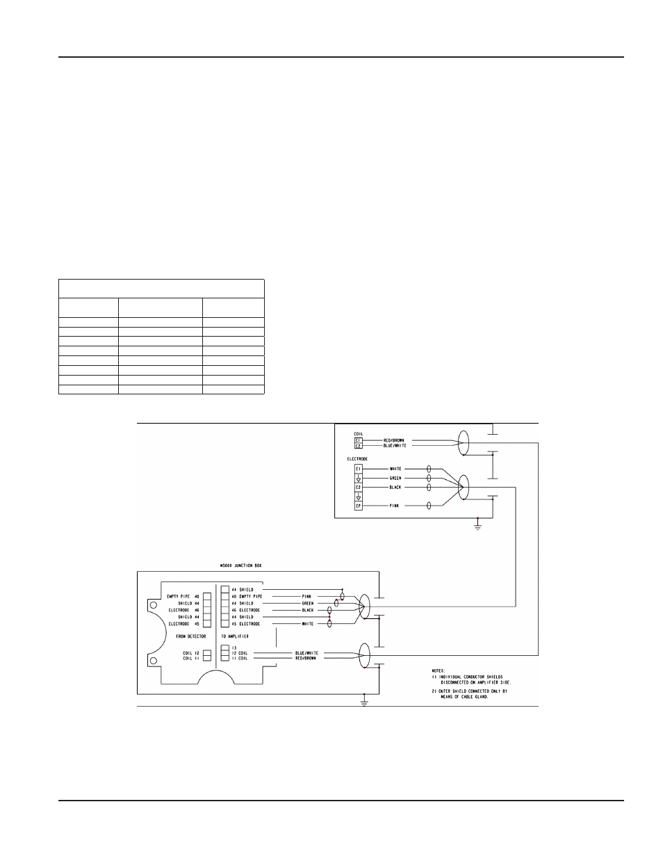
Wiring for Remote Configuration
Remote style M5000 amplifier models can be ordered with standard cables measuring 15, 30, 50 and 100 feet .
Junction Box
Connection
No.
Description
Wire Color
11
Coil
Red/Brown
12
Coil
Blue/White
13
Main Shield
Not Used
40
Empty Pipe
Pink
44*
Shield
Green
44*
Empty Pipe Shield
Shield Wire
45
Electrode
White
46
Electrode
Black
*Connections with the No . 44 are lying on the same potential .
M5000 AMPLIFIER
Figure 20: Wiring for Remote Configuration
Battery
MAG-UM-00219-EN-03
Page 15
August 2014