Amplifier mounting configuration options, Meter mount configuration, Remote mount configuration – Badger Meter M-Series M5000 User Manual
Page 13: Submersible option, Wiring, Wiring safety, Opening the m5000 cover, Wiring safety opening the m5000 cover
AMPLIFIER MOUNTING CONFIGURATION OPTIONS
Meter Mount Configuration
The meter mount configuration has the amplifier mounted directly on the detector . This compact, self-contained
configuration minimizes installation wiring .
Remote Mount Configuration
The remote mount configuration places the amplifier at a location away from the fluid flow and detector . This is necessary in
situations where process fluid temperature or the environment exceeds amplifier ratings .
The detector and amplifier are connected by wires, run through conduit, between junction boxes on the detector and the
amplifier . The distance between the detector junction box and amplifier junction box can be up to 100 feet (30 meters) . A
remote mounting bracket is supplied .
Submersible Option
If you are installing the meter in a vault, you should order the remote amplifier option . You must not install the amplifier inside
a vault . We also recommend ordering the remote meter package with the submersible option (NEMA 6P) . This will eliminate
any potential problems resulting from humidity or temporary flooding in the vault .
OTEE:
N
NEMA 6P enclosures are constructed for indoor or outdoor use to provide protection against access to hazardous
parts; to provide a degree of protection against ingress of solid foreign objects and water (hose directed water and
the entry of water during prolonged submersion at a limited depth); that provide an additional level of protection
against corrosion and that will be undamaged by the external formation of ice on the enclosure .
WIRING
Wiring Safety
AT INSTALLATION, BE SURE TO COMPLY WITH THE FOLLOWING REQUIREMENTS:
• Disconnect power to the unit before attempting any connection or service to the unit .
• Do not bundle or route signal lines with power lines .
• Keep all lines as short as possible .
• Use twisted pair shielded wire for all output wiring .
• Observe all applicable, local electrical codes .
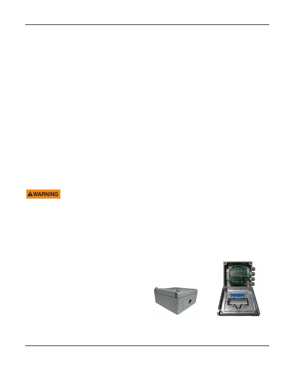
Opening the M5000 Cover
The M5000 amplifier's design lets you open the cover
without completely removing it .
Follow these steps:
1 . Completely remove the top two screws from the
amplifier using a blade/slotted screwdriver .
2 . Loosen both of the bottom screws so that the round
head of each screw clears the top face of the cover .
3 . Pull the cover down to the open position .
Figure 17: Remove Two Screws
Figure 18: Open the Cover
Amplifier mounting configuration options
MAG-UM-00219-EN-03
Page 13
August 2014