Technical data 48 – West Control Solutions SG 45 User Manual
Page 48
9.2
Calibration (
CAL)
+
Before calibration, allow the unit to warm up (see Technical Data on page 54).
After delivery, a % value is displayed as a measured value (related to the adjusted measuring range).
For this reason, the Uniflex SG 45 must be adapted to its measuring task accordingly. To adapt the unit, realize the cal -
ibration correctly.
+
If necessary, the required display unit (
D.Unt) must be selected accordingly.
g
Load cells: the dead load (raw value) provides a signal. Set
InL.1 = 0 to set this signal to zero (span start).
g
With pressure sensors, the sensor should be de-pressurized, or pressure setting for span start:
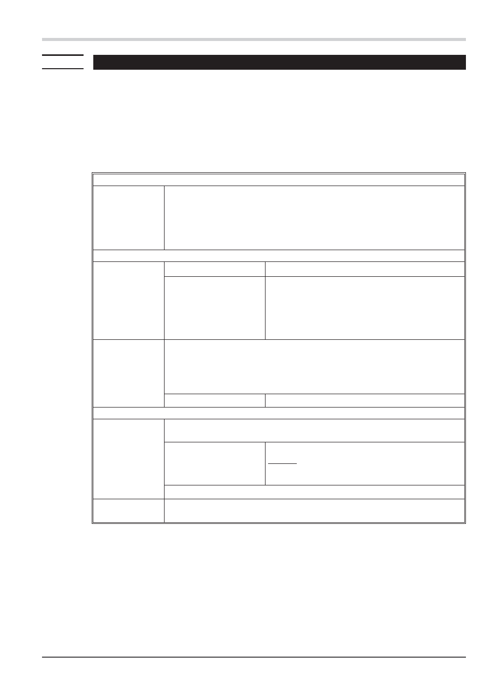
Calibration 1. step: Define span start
Display
:
InL.1 = OFF
Press keys
p/q
to display the current measurement value.
InL.1 = % measured value (display changes between InL.1 and instantaneous mea-
sured value). With
ô followed by storage of
InL.1 = instantaneous measured value,
related display value OuL.1 = 0
When the enter key ô is pressed immediately, without pressing
p/q the increment / decre-
ment keys, InL.1 = 0 %, OuL.1 = 0 is taken over as standard value.
Calibration 2. step: Define calibration value
g
Load cell
melt pressure sensors:
Load load cells with a defined
load (reference weight; e.g.
75kg)
Enter pressure for span end or a defined known calibration
value.
For sensors with integrated calibration resistor an automatic
switching of the calibration resistor is done.
For the first calibration
SEtit is recommended to configure
CAL.M = 1 , -> S. 47
InH.1 = OFF
Press keys
p/q
to display the instantaneous measured value.
InH.1 = swaps with the
display of the measured value
With the enter key
ô
the instantaneous mesured value is taken over to
InH.1
When the enter key
ô is pressed immediately, without pressing p/q the increment / de-
crement keys
,
InH.1 = 100 %, OuH.1 = Out.1 is taken over.
(The calibrating resistor is switched off automatically)
Calibration 3. step: Calculation of the upper calibrationpoint
OuH.1
With
OuH.1
the upper calibrating point is realized using the
p/q keys according to
the calculated value
Calculation for calibrating resistor (e.g. 80% )
Example: The calibrating resistor has a range from 0..400
Bar; the calibrating resistor simulates 80% of the endvalue,
80% of 400 results 320.
OuH.1is adjusted to 320.
Press
ô
to store OuH.1 = adjusted upper calibration point
g
DonE
donE (duration 1s) storage of InL.1, OuL.1, InH.1, OuH.1 takes place. Additionally, any
previously realized zero setting (function 1) is deleted.
+
A tare function activated before calibration must be de-activated. Normally, it is not purposeful to keep the old tare
condition. If necessary, the tare function can be re-activated.
The zero offset is deleted automatically.
+
The InL.1 and InH.1 values stored during calibration are stored with full resolution.
Installation and calibration
48
Calibration (
CAL)
SG 45