13 integrator function 29, 14 limit value processing 29, Limit 29 - 32 – West Control Solutions CI 45 User Manual
Page 29
6.13
Integrator function
The input signal can be totalized by means of a selectable integrator (
ConF \ Func \ Fnc.3 = 3).
Function:
Integrator with adjustable time constant (
PArA \ Func \ t.I) [specified in minutes] and adjustable input offset
(
PArA \ Func \ P.I)
Formula:
y(t) = y(t-Tr) + Tr/t * (x +P.I)
y(t)
= integrator output
y(t-Tr)
= integrator output of the last cycle
Tr
= cycle time (100ms INP1, 140ms INP1 + INP2)
t
= time constant
x
= integrator input
P.I
= input offset (zero offset)
g
With a constant input value, the integrator output reaches the specified value after elapse of the adjusted time
constant t.I.
Reset:
Dependent on selection (
ConF\Logi\rES.I), the integrator can be reset via:
w
Digital input di1
w
Key combination Enter + increment key
(keep the Enter key pressed and actuate the increment key)
w
Limit values Limit1 to Limit3
Example 1:
A flow in m
3
/h is measured. The integrator should measure the overall flow quantity. The measured flow is related to
time unit hours, i.e. time constant t.I = 1 hour = 60 min must be used. Parameter P.I can be used for zero correction.
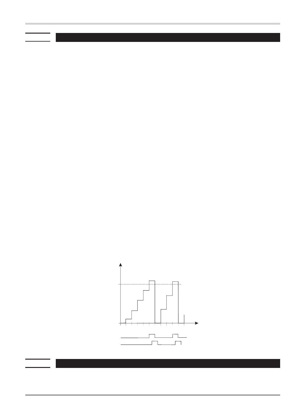
Example 2: pulse output
The integrator is activated. The resulting process value is monitored using a limit value (without memory) , e.g. Lim1.
Lim.1 is defined as integrator reset function. Limit value Lim.1 is output e.g. on ouput 1 (OUT.1).
When exceeding limit value Lim1, there is a signal change at OUT1 during a period (100ms INP1, 140ms INP1 + INP2).
6.14
Limit value processing
Max. three limit values can be configured for the outputs. Generally, each one of outputs
Out.1... Out.3 can be
used for limit value or alarm signalling. Several signals allocated to an output are linked by a logic OR function.
Functions
UNIFLEX CI 45
Integrator function
29
P.I
H.1
x
t (cycle)
Lim.1
Out.1