Electrical connections 10, 1 connecting diagram 10, 2 terminal connections 10 – West Control Solutions CI 45 User Manual
Page 10: Connecting diagram 10, Terminal connections 10 - 11, Electrical connections 4.1, Connecting diagram, Terminal connections
.
4
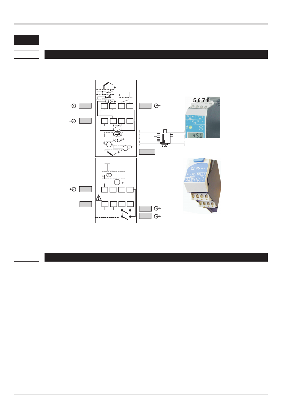
Electrical connections
4.1
Connecting diagram
4.2
Terminal connections
a
Faulty connection might cause destruction of the instrument !
1 Connecting the supply voltage
Dependend on order
w
90 … 260 V AC
terminal: 15, 16
w
24 V AC / DC
terminal: 15, 16
For further information, see section
"Technical data"
g
Instruments with optional system interface:
Energization is via the bus connector of field bus coupler or power supply module. Terminals 15, 16 must
not be used.
Electrical connections
- preliminary -
10
Connecting diagram
UNIFLEX CI 45
Data A
Data A
Data B
Data B
V
14
13
12
16
15
11
mV
17 18
INP2
INP1
OUT3
PWR
L
N
OUT1
OUT2
90...260V AC
24V AC/DC
di1
8
7
6
3
2
1
5
3
4
(mV)
RGND
RGND
RS 485
1
2
a
3
4
5
6
7
b
c
d
e
f
g
a
b
c
d
a
b
Logic
V
h
i
j
k
e
11 12 13 14
11 12 13 14
15 16 17 18
15 16 17 18
1 2 3 4
1 2 3 4
top
See also other documents in the category West Control Solutions Equipment:
- 2300 (18 pages)
- 3300 (2 pages)
- 4100+ (177 pages)
- N4100 (79 pages)
- N4400 (38 pages)
- N6500 (2 pages)
- N6600 (114 pages)
- N8800 (88 pages)
- N8840 (90 pages)
- 9300 (2 pages)
- 9500 (24 pages)
- D280-1 (49 pages)
- KS 40-1 (60 pages)
- KS 40-1 Burner (40 pages)
- KS 45 (76 pages)
- KS 50-1 (72 pages)
- KS 90-1 (84 pages)
- KS 90-1 Programmer manual (84 pages)
- KS 94 (44 pages)
- ProVU 4 (184 pages)
- Pro-16 (88 pages)
- Pro-8 (72 pages)
- Pro-4 (84 pages)
- ProEC44 (274 pages)
- SG 45 (56 pages)
- DataVU 5 (136 pages)
- DataVU 7 (208 pages)
- MRC 5000 Controller Manual (32 pages)
- MRC 5000 Recorder Manual (32 pages)
- MRC 7000 Controller Manual (74 pages)
- MRC 7000 Recorder Manual (64 pages)
- MRC 7000 Profiler Manual (84 pages)
- MRC 8000 (76 pages)
- MRC 9000 (318 pages)
- N8080 (for 1xxx) (40 pages)
- N8080 (for 2xxx) (39 pages)
- TB 40-1 Temperature Limiter (32 pages)
- TB 40-1 Temperature Monitor (32 pages)
- TB 45 Temperature Limiter (51 pages)
- TB 45 Temperature Monitor (52 pages)
- CALogix (44 pages)
- KS 800 Operating Instructions (36 pages)
- KS 800 ISO1745 Interface Manual (34 pages)
- KS 800 Profibus Interface Manual (52 pages)