1 input fail detection 21, 2 two-wire measurement 21, 3 scaling with potentiometer measurement 21 – West Control Solutions CI 45 User Manual
Page 21: Input fail detection 21, Two-wire measurement 21
a
For using the pre-defined scaling with thermocouples and resistance thermometers (Pt100), the settings
for
InL and OuL as well as for InH and OuH must correspond with each other.
+
For resetting the input scaling, the settings for
InL and OuL as well as InH and OuH must
correspond.
6.2.1
Input fail detection
For life zero detection of connected input signals, variable adjustment of the response value for FAIL detection is
possible according to formula:
Fail response value
£ In.L - 0,125 * (In.H - In.L)
Example 1:
In.L = 4 mA, In.H = 20 mA
Fail response value
£ 2 mA
Example 2:
In.L = 2 V, In.H = 6 V
Fail response value
£ 1,5 V
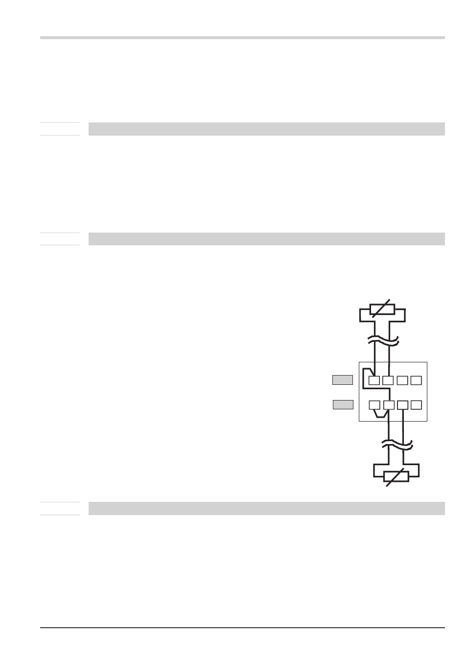
6.2.2
Two-wire measurement
Normally, resistance and resistance thermometer measurement is in three-wire connection, whereby the resistance of
all leads is equal.
Measurement in four-wire connection is also possible for input I. With this method, the lead resistance is determined
by means of reference measurement.
With two-wire measurement, the lead resistance is included directly as a falsification in the measurement result.
However, determination of the lead resistances by means of is possible.
g
Besides the connection of the both leads of the RTD / R sensor the
3rd connector has to be short-circuited.
Procedure with Pt100, Pt1000
Connect a Pt100 simulator or a resistance decade instead of the sensor at
the test point so that the lead resistance is included and calibrate the
values by means of 2-point correction.
+
By means of measurement value correction the resulting
temperature value will be corrected, but not the resistance input
value. In this case the linearization error can increase.
Procedure with resistance measurement
Measure the lead resistance with an ohmmeter and subtract it from the
measured value via the scaling.
6.2.3
Scaling with potentiometer measurement
With potentiometer measurement (
S.tYP = 50 … 53), a display value in 0% (lower stop value) to 100 % (upper stop
value) is normally expected.
For this, 2-point calibration at calibrating level (rp. 49) Is necessary.
Turn your potentiometer to the lower stop and specify value “0” for
OuL.x. Now, turn the potentiometer to the upper
stop and set value
OuH.x to “100”.
Functions
UNIFLEX CI 45
Input scaling
21
INP2
INP1
8
7
6
3
2
1
5
3
4
1
2