West Control Solutions N4400 User Manual
Page 30
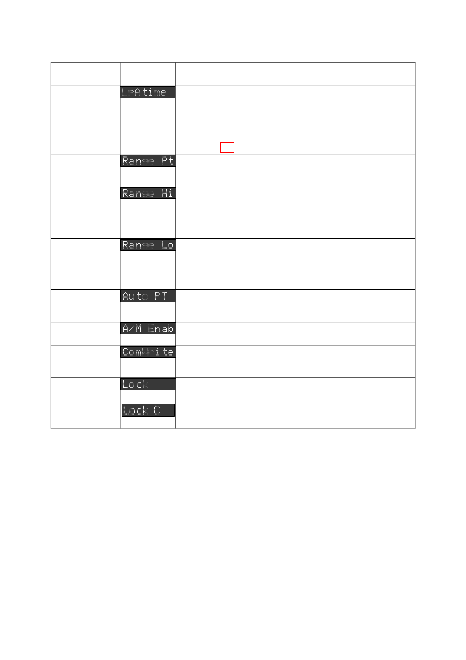
Parameter
Message
Display
Function
Available Settings/Values
(Lower Main Display)
Loop Alarm Time
If ON/OFF control is selected
(i.e PB1 = 0) and Loop Alarm is
enabled, this defines the
duration of the saturation
condition after which the Loop
Alarm is activated (see
Subsection 9.3)
1sec. to 99mins. 59secs.
Default = 99mins. 59secs.
Scale Range
Decimal Point
Position
9
For linear inputs, defines the
decimal point position.
0 (xxxx)
1 (xxx.x)
2 (xx.xx)
3 (x.xxx)
Default = 1 (xxx.x)
Scale Range
Maximum
9
For linear inputs, defines the
scaled input value when the
process variable input is at its
maximum value.
−
1999 to 9999 (decimal point
position as defined by Scale
Range Decimal Point Position
parameter).
Default = 100.0
Scale Range
Minimum
9
For linear inputs, defines the
scaled input value when the
process variable input is at its
minimum value.
−
1999 to 9999 (decimal point
position as defined by Scale
Range Decimal Point Position
parameter).
Default = 0.0
Auto Pre-Tune
Enable/Disable
Determines whether the
Pre-Tune facility is activated
automatically at power-up.
OFF = disabled; On = enabled.
Default = OFF (disabled).
Manual Control
Enable/Disable
Enables/disables operator
selection of Manual Control.
OFF = disabled; On = enabled.
Default = OFF (disabled).
Communications
Write
Enable/Disable
10
Enables/disables changing of
parameter values or settings via
the RS485 Communications link
OFF = disabled;
On = enabled.
Default = OFF (disabled).
Lock Value
12
or
Defines the four-digit code
required to enter Controller
Define Mode (and, if a common
lock code is used, Program
Define Mode).
0 to 9999.
Default = 10.
NOTES ON CONTROLLER DEFINE MODE PARAMETERS
1. The Process Variable Offset value should be chosen with care. Any adjustment to this parameter
is, in effect, a calibration adjustment. Injudicious application of values to this parameter could lead to
the displayed process variable value bearing no meaningful relationship to the actual process variable
value. There is no front panel indication when this parameter is in effect (i.e. has been set to a
non-zero value).
2. These parameters are applicable only if the secondary Control (COOL) ooutput is fitted.
3. These parameters are not applicable if Proportional Band 1 is set to 0 (i.e. ON/OFF control for
Output 1).
4. This parameter is not applicable if Proportional Band 1 is set to 0 or if Output 2 (COOL) is not fitted.
5. The Message Display will show Diff 1 for ON/OFF control on Output 1, Diff 2 for ON/OFF control
on Output 2 or Diff for ON/OFF control on both Output 1 and Output 2.
Page 9-5
59215-9
59215