2 connection diagram, Onnection, Iagram – Thermo Fisher Scientific Alpha pH 2000D User Manual
Page 15
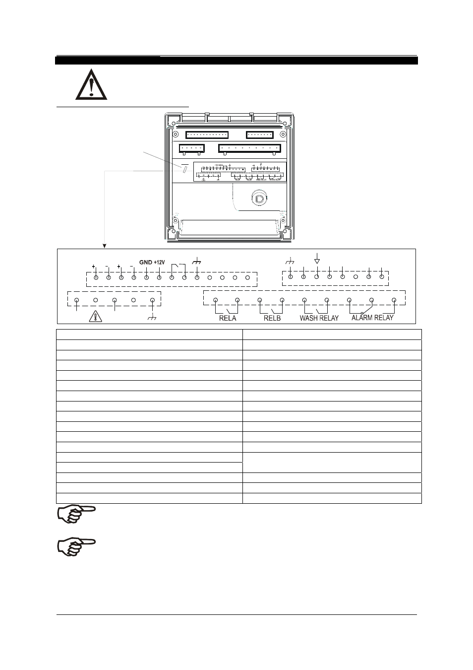
3.2 Connection
Diagram
Caution: Ensure electrical mains are disconnected before proceeding
.
Connections for wall mounting version
1
L
2
N
Current
15
Current
13
OP2
14
16
OP1
17
3
4
5
6
22
HOLD
18
19
21
20
23
24
25
7
8
9
10
11
29
26
28
27
30
31
32
33
12
-5 V
TEMP
SENS TEMP
pH
REF
pH
MEAS
Fuse: 250V 315 mA,
Time Delay
L
1
12
24
Current
N
OP2
13
Current
14
2
15
16
OP1
17
3
21
HOLD
18
19
20
4
22
23
28
5
25
6
7
26
27
8
-5V
TE MP
31
TE MP
S ENS
29
9
30
10
p H
RE F
11
32
33
pH
ME A S
250V, 315 mA,
Time Delay
1.
AC mains live wire
18.
12V output Power supply
2.
AC mains neutral wire
19.
Hold Function
3.
AC mains protective earth wire
20.
Hold Function
4.
Relay A (SP 1)
21.
Earth ground
5.
Relay A (SP 1)
22.
no connection
6.
Relay B (SP 2)
23.
no connection
7.
Relay B (SP 2)
24.
no connection
8.
Wash relay
25.
no connection
9. Wash
relay
26.
Shield
(drain wire)
10.
Alarm relay (NC)
27.
-5V to differential pH sensor (White wire)
11.
Alarm relay common
28.
Temperature ground (black wire)
12.
Alarm relay (NO)
29.
Temperature Sense (Yellow wire)
13.
4-20 mA temperature output, +ve terminal
30.
Temperature Input (Yellow wire)
14.
4-20 mA temperature output, -ve terminal
(Internally connected by jumper to terminal 29)
15.
4-20 mA pH/ORP output, +ve terminal
31.
No connection
16.
4-20 mA pH/ORP output, -ve terminal
32.
pH input, Reference (Green wire)
17.
12V output ground
33.
pH input, Measure (Red wire)
IMPORTANT: The Alarm relay functions
“A
s OFF under
as an
ctive Low” device i.e. it switche
Alarm condition. Therefore the Alarm display device should be connected to the ‘NC’ contacts of
the relay (10 & 11).
h or circuit breaker shall be included in the building installation.
the operator.
NOTE:
a)
Switc
b)
It shall be in close proximity to the equipment and within easy reach of
c)
It shall be marked as the disconnecting device for the equipment.
- 10 -