KYORITSU 4106 User Manual
Page 36
32
(e.g. The spike should be stuck in the depth of 25cm or less when the
interval of the Auxiliary Earth Spikes is 5m.)
If the Spikes stuck too deep, it may result in inaccurate earth resistivity
measurement.
Note) The supplied Test Leads MODEL 7229 can be used for the Spikes
stuck at the interval of max 20m.
Note) The length of the supplied Auxiliary Earth Spike MODEL 8032 is
20cm.
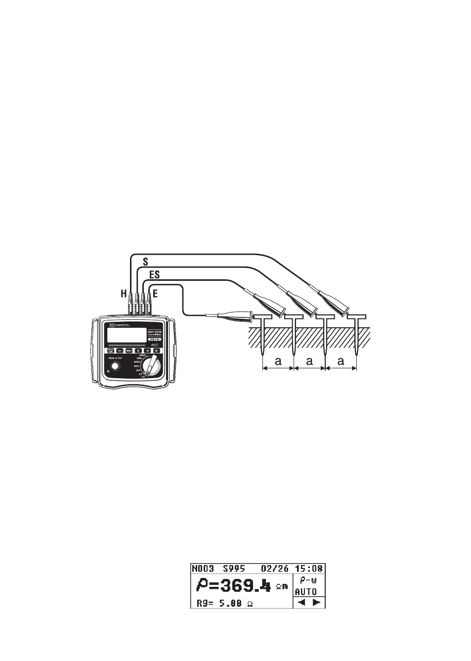
Connect the green, black, yellow Test Leads connected to the “E”, “ES”,
“S(P)” and “H(C)” Terminals on the instrument to the Auxiliary Earth Spikes
from the closest to the farthest in this order. (Fig.41)
(3) Setting of the Interval between Auxiliary Earth Spikes
The interval of the Spikes should be entered according to the setting
made at the step of “8-2-5 Setting for the interval between Auxiliary
Earth Spikes at Earth Resistivity (ρ) Measurements”.
(4) Earth Resistivity (ρ) Measurement
Select a Range (any Range is ok) when the connection is done, and
press the TEST Button. Then the measured earth resistivity (ρ) and
the earth resistance “Rg” between the ES-S Terminals are displayed.
(Fig.42)
Fig. 42
Fig. 41