KYORITSU 4106 User Manual
Page 34
30
(1) Setting of Wiring System
Select “Wire (2)” with reference to “8-2-2 Setting for Measurement
Method” in this manual.
(2) Setting of Rk
1. Put the Alligator Clips to the 2 Test Leads (green, red), and connect
the green Plug to the “E” Terminal and the two red Plugs to the
“S(P)” and “H(C)” Terminals respectively.
2. Select the “2Ω” or ”20Ω” Range.
3. Engage 2 Alligator clips to short-circuit both of them.
4. Save the Rk values with reference to “8-2-7 Setting for the residual
resistance (Rk) on the Test Leads”.
Note) A break in Test Leads or burnout of Fuse is suspected when the
LCD shows “Rk=OL Ω” while 4 Test Leads are being shorted.
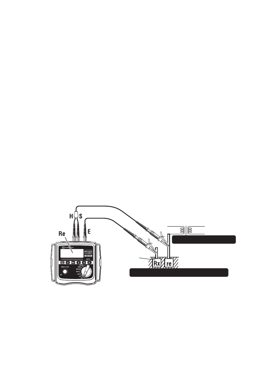
(3) Connection
Connect the Test Leads as shown in Fig.40.
Note) When the supplied Simplified Measurement Probes are not used, the
“S(P)” and “H(C)” Terminals should be shorted.
(4) Earth Resistance Measurement
Select a high resistance Range when the connection is done, and press
the TEST Button. Then the earth resistance values “Re” are displayed
on the LCD. Select a lower Range for the low earth resistances.
Red
Green
Earthed
Electrode
under Test
Secondary
Primary
Side
Side
Indicated
Value
Be sure to check
earthed side of
a commercial
power supply.
Supply Transformer
Where earth for mains supply is used.
Fig. 40