KYORITSU 4106 User Manual
Page 29
25
9-1-1 Precise Measurement (3-Wire) * with Earth Test Leads MODEL 7229
This is a standard method to measure earth resistances. The measured earth
resistances are free of auxiliary earth resistances but the resistances on the
E terminal are contained.
Terminals to be used : E, S(P), H(C) Terminals
Test Leads
: connect to the E, S(P), H(C) Terminals
Auxiliary Earth Spike : 2 pcs, connect to the S(P) and H(C) terminal
(1) Setting of Wiring System
Select “Wire (3)” with reference to “8-2-2 Setting for Measurement
Method” in this manual.
(2) Setting of Rk
1. Firmly insert each plug of 3 test leads (green, yellow, red) to the
corresponding connectors on the instrument.
2. Select the “2Ω” or ”20Ω” Range.
3. Engage 3 Alligator clips to short-circuit all of them.
4. Save the Rk values with reference to “8-2-7 Setting for the residual
resistance on the Test Leads”.
Note) A break in Test Leads or burnout of Fuse is suspected when the
LCD shows “Rk=OL Ω” while 3 Test Leads are being shorted.
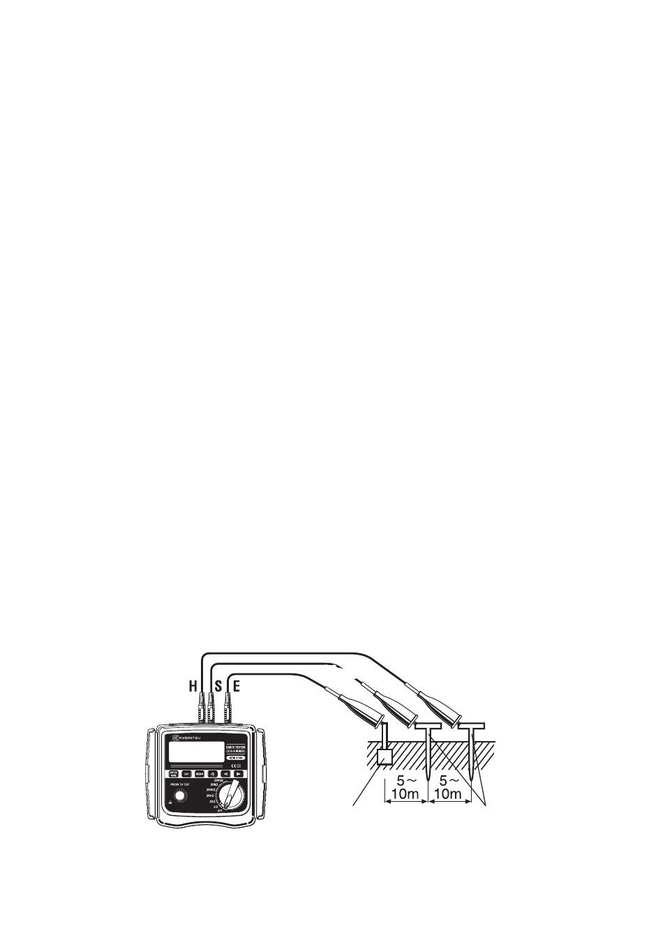
(3) Connection of Auxiliary Earth Spikes and Test Leads
Stick the Auxiliary Earth Spikes “S(P)” and “H(C)” into the ground
deeply. They should be aligned at an interval of 5-10m from the earthed
equipment under test. Connect the green Test Lead to the earthed
equipment under test, the yellow Test Lead to the Auxiliary Earth Spike
“S(P)” and the red Test Lead to the Auxiliary Earth Spike ”H(C)”.
(Fig.34)
Yellow
Yellow
Red
Green
Earthed Electrode
under Test
Auxiliary
earth spikes
Fig. 34