KYORITSU 4106 User Manual
Page 32
28
(2) Setting of Rk
The measured results obtained at 4-Wire system are not be influenced
by the Test Leads Connected to the “E” Terminal, but setting of Rk can
be made on this instrument.
1. Firmly insert each plug of 4 Test Leads (green, black, yellow, red), to
the corresponding connectors on the instrument.
2. Select the “2Ω” or ”20Ω” Range.
3. Engage 4 Alligator clips to short-circuit all of them.
4. Save the Rk values with reference to “8-2-7 Setting for the residual
resistance (Rk) on the Test Leads”.
Note) A break in Test Leads or burnout of Fuse is suspected when the
LCD shows “Rk=OL Ω” while 4 Test Leads are being shorted.
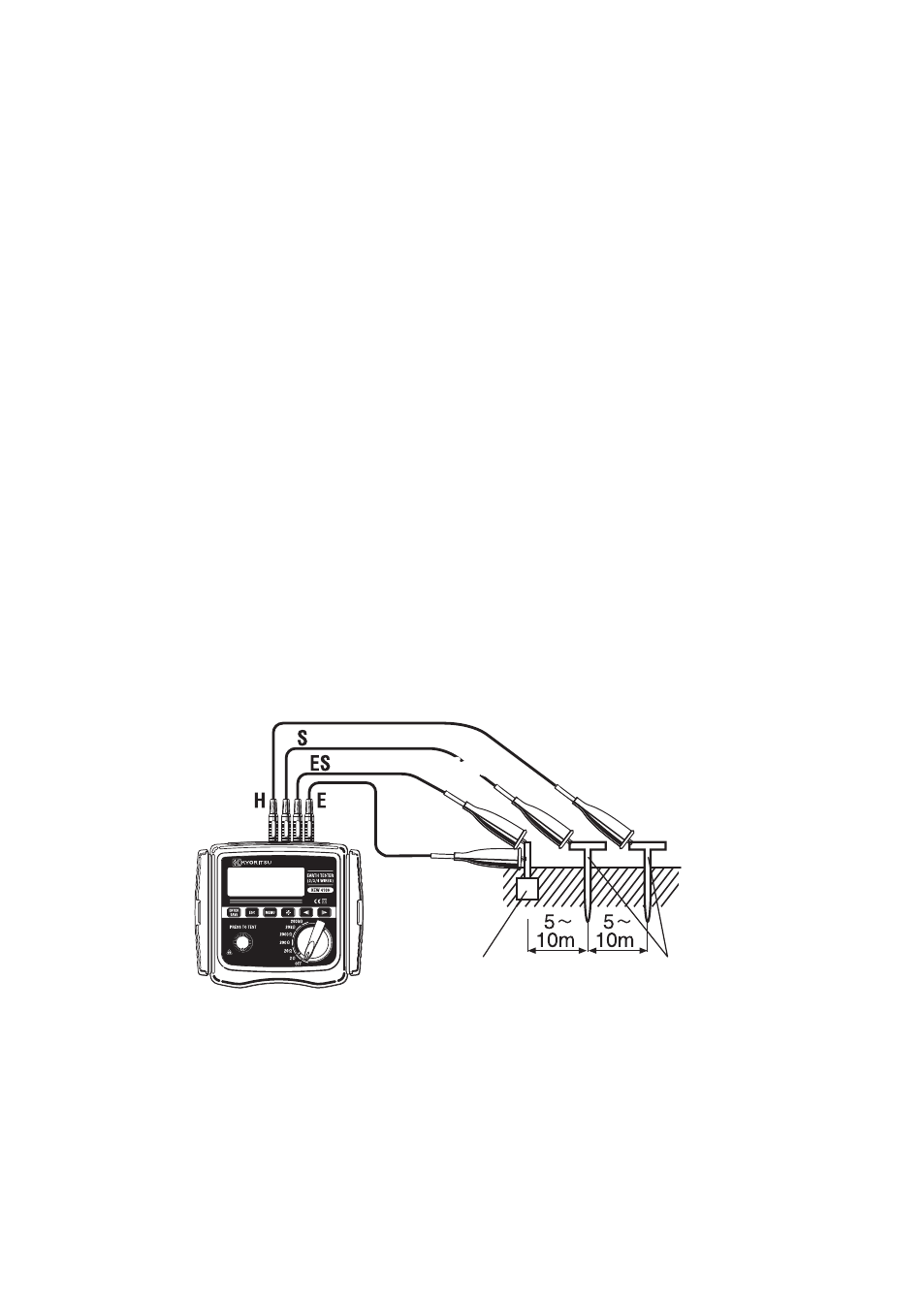
(3) Connection of Auxiliary Earth Spikes and Test Leads
Stick the Auxiliary Earth Spikes S(P) and H(C) into the ground deeply.
They should be aligned at an interval of 5-10m from the earthed
equipment under test. Connect the green Test Lead to the earthed
equipment under test, the yellow Test Lead to the Auxiliary Earth Spike
S(P) and the red Test Lead to the Auxiliary Earth Spike H(C).
The black Test Lead connected to the “ES” Terminal should be
connected to the earthed equipment under test. (Fig.39)
(4) Earth Resistance Measurement
Select a Range (any Range is ok) when the connection is done, and
press the TEST Button. The measured earth resistances “Re” are
displayed on the LCD. The operation procedure is same to that for
3-Wire measurements.
Fig. 39
Yellow
Yellow
Red
Green
Earthed Electrode
under Test
Auxiliary
earth spikes