HT instruments SIRIUS87 User Manual
Page 39
SIRIUS
87
EN - 37
4.4.4. Mode "P-PE"
1. Select
P-PE mode by means of the FUNC key.
2. Connect the 3 black, blue and green connectors of the three-terminal shuko cable or of the
single cables in the corresponding input terminals of the instrument
B1, B3, B4 (see Fig. 12,
Fig. 13, Fig. 14). When using untied cables connect the crocodiles to the free ends of the
cables.
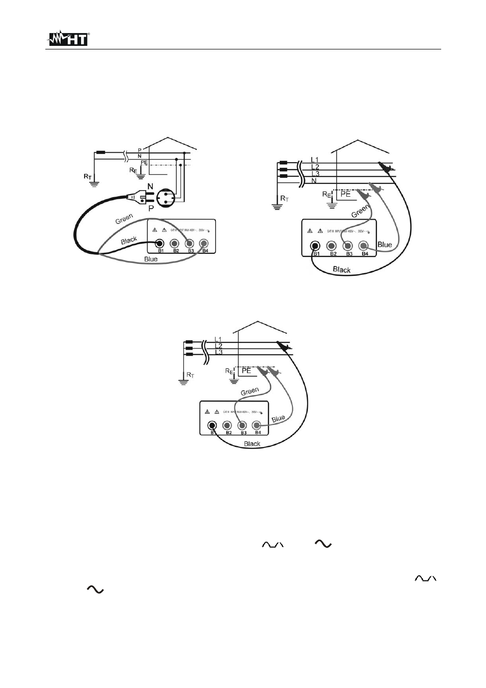
Fig. 12: Connection for P-PE impedance
measurement Single/Two phase 230V
Fig. 13: Connection for P-PE impedance
measurement Three-phase 400V + N
Fig. 14: Connection for P-PE impedance measurement Three-phase 230/400V without N
3. Connect the shuko plug into a 230V 50Hz socket or the crocodiles to the conductors of
the three-phase system (see Fig. 12, Fig. 13, Fig. 14).
4. The instrument carries out the test verifying that the contact voltage of the installation
masses relating to the current actually supplied by the instrument is not higher than the
limit contact voltage value. The limit contact voltage which reference is made to is that
set under one of the following functions: RCD
, RCD
or R
a15mA
.
Example: if you are effecting some tests in a medical room, the limit contact voltage is
equal to 25V. The operator will switch on one of the following functions: RCD
,
RCD
or Ra
15mA
, and select the limit contact voltage of 25V by means of U
L
t. At
this stage if you turn the selector on LOOP Z
S
/I
K
under mode P-PE, the instrument will
refer to the limit of 25V during the test.