Caution – HT instruments SIRIUS87 User Manual
Page 38
SIRIUS
87
EN - 36
4.4.3. Mode "P-P"
1. Select
P-P mode by means of the FUNC key.
2. If possible disconnect all low impedance loads downstream the point at which the
measurement is to be taken, as such an impedance would be in parallel with the line
impedance to be measured.
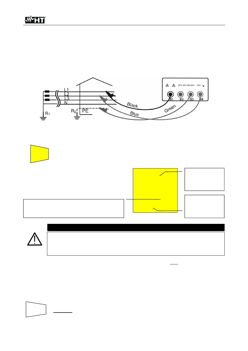
3. Connect the 3 black, green and blue connectors of the single cables in the corresponding
input terminals of the instrument
B1, B3, B4 (see possible connections in the following
pictures). When using untied cables connect the crocodiles to the free ends of the cables.
Fig. 11: Connection for P-P impedance measurement Three-phase 400V
4. Connect the crocodiles to the conductors of the three-phase system (see picture).
5. Press
the
START/STOP key. The instrument starts the test.
At the end of the test the instrument
emits a
double sound signal
indicating that the test is correctly
terminated and displays the values
alongside.
LOOP
1.07
P-P
383
V
374
A
CAUTION
The measurement of Phase-Phase impedance entails the following of a
current of about 11.5A between the above said conductors. This may cause
the tripping of magnetothermal RCDs with nominal value lower than 10A. If
necessary effect the test upstream the RCD itself.
Formula for calculation of prospective short circuit current:
PP
N
CC
Z
U
I
where
U
N
= phase to phase voltage 127V if V
meas
150V
230V if 150V < V
meas
265V
400V if V
meas
> 265V
SAVING:
The tests can be stored pressing the
SAVE key twice
(according to § 5.1).
Value of phase to
phase line
impedance
expressed in
.
Phase to phase
effective voltage
value expressed
in Volt.
Effective value of the phase to phase prospective
short circuit current expressed in Ampere
calculated according to the following formula.
SAVE
START
STOP