Caution – HT instruments SIRIUS87 User Manual
Page 18
SIRIUS
87
EN - 16
4.2.1. Procedure to measure insulation resistance in any modes
1. Select the desired mode by means of the
FUNC key.
2. Connect the black and blue cables to the instrument input terminals
B1 and B4
respectively
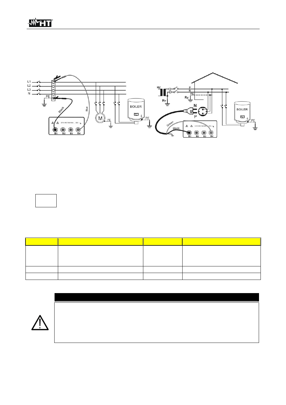
Fig. 3 Insulation P-PE with untied cables
Fig. 4 Insulation P-PE with Shuko cable
3. If the cables supplied with the instrument are not long enough for the measurement you can
extend the blue cable.
4. Connect the instrument terminals to the object which is to be submitted to the insulation
test
after disconnecting the circuit under test and all the relative loads (see Fig. 3,
Fig. 4)
5. By
means
of
U
n
/I
n
select the test voltage suitable for the type of test
to be carried out (see table). The values to be selected are:
50V (test on telecommunication system)
100V
500V
250V
1000V
Standard
Brief description
Test voltage
Maximum limit value
CEI 64-8/6
Systems SELV or PELV
Systems up to 500V (Civil installations)
Systems over 500V
250VDC
500VDC
1000VDC
> 0.250M
> 1.000M
> 1.000M
EN60439
Electrical panel boards 230/400V
500VDC
> 230k
EN60204
Electrical equipment of machines
500VDC
> 1M
Table 1: Test voltage values and limit values for the most common kinds of test
CAUTION
If
“Measuring” is displayed the instrument is effecting the measurement.
During this phase do not disconnect the test leads as the circuit under test
may remain charged at a dangerous voltage due to the parasite capacities of
the installation. Independently of the working mode selected the instrument
throws a resistance in the output terminals at the end of each test to
discharge the parasite capacities of the circuit.
U
n
/I
n
DIST