HT instruments SOLAR I-V User Manual
Page 50
I-V400 - SOLAR I-V
EN - 48
8. Press ENTER key and by means of arrow keys (
,)
select the item “Meas. Type ”
9. By means of arrow key
access the internal submenu,
select the item “RS Test” and confirm with ENTER to
open the main screen of Rs measurement.
15/05/10 15:34:26
V d c = 0 . 0 V
I r r = 0 W / m 2
T c = - - - ° C
Module: SUNPOWER 210
S e t
R S T e s t
M e a
I - V T e s t
Select
I - V
10. The herewith screen is shown on the display, where:
Rs = serial resistance
Vdc = DC output voltage from module
Irr = irradiance measured by supplied reference cell
Module = active module
15/05/10 15:34:26
R s
V d c
I r r
= - - -
= 0 . 0 V
= 0 W / m 2
Module: SUNPOWER 210
Select
RS Mode
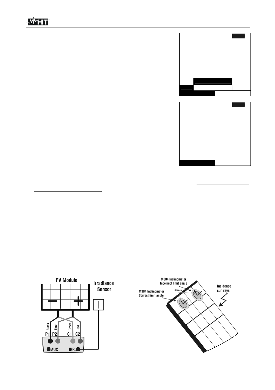
11. Mount the M304 (inclinometer) supplied accessory, position and hold it on the plane of
module. Verify that the sun shadow falls on the disc within the “limit internal circle”
on the disc itself (Fig.12b). If this is not the case the incidence angle between sun
rays and the module surface is too high and not complying with the test conditions
declared by the module manufacturer. As a consequence the measurements
performed by the meter are not ok and all measurements steps shall be repeated at
another daytime.
12. Connect the MONO or MULTI output (depending on the type of module under test) of
reference cell at the IRR. input of meter by using the cable supplied with the cell.
13. Fix the support of the cell to the module by using the supplied set of screws and mount
the reference cell on it possibly with output terminals downwards with respect to
the module. Rotate the cell upwards to lean it on the small wing of the support to have
it perfectly parallel to the module plane, then fix it with the relevant screws supplied.
14. Connect the meter to the module/string under test as shown in Fig.12a In particular,
connect the negative output pole of module/string to P1, C1 input terminals and the
positive output pole of module/string to P2, C2 input terminals
Fig. 12a: Instrument connection to module FV Fig. 12b: Positioning inclinometer M304