Caution – HT instruments SOLAR I-V User Manual
Page 46
I-V400 - SOLAR I-V
EN - 44
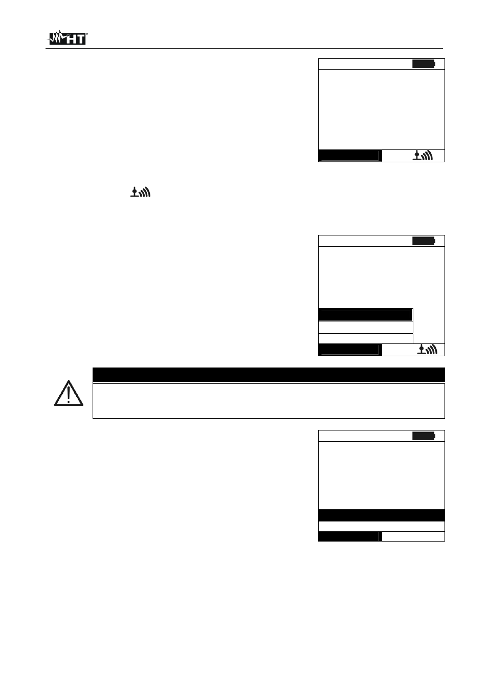
22. The instrument displays a screen similar to the one
reported here to the side, where:
Vdc = DC output voltage from module/string
Irr = irradiance measured by supplied reference cell
Tc = temperature of module. The herewith options are
available for this field:
AUTO automatic mode of temperature measurement
Number MAN or AUX mode of temp. measurement
“ - - - “ AUX mode with no connected probe
Module = type of selected module
Temp = measurement mode of module temperature
The symbol “
” fixed at display means that a stable
RF connection is established with the remote unit
SOLAR-02
15/05/10 15:34:26
V d c = 3 6 7 V
I r r = 1 0 4 5 W / m 2
T c = 4 5 ° C
Module: SUNPOWER 210
Select
I – V
23. Press ENTER key, select the “Activate Rec.” item and
confirm with ENTER. The message “Remote unit in
recording…” is displayed on the meter. In this condition is
possible to start the I-V curve tests always considering
that the complete results will be available only after the
stop of recording of SOLAR-02 and transfer them from the
same remote unit
15/05/10 15:34:26
V d c = 0 . 0 V
I r r = - - - W / m 2
T c = - - - ° C
A c t i v a t e R e c .
S e t t i n g s
M e a s . T y p e
Select
I – V
CAUTION
At the press of GO/STOP key some different error messages can be
displayed by the meter (see § 6.4) and, due of this, the test cannot start.
Check and remove, if possible, this error message before start the test
24. Press GO/STOP key to start the test. If none of the
previous error messages are detected, the message
“Measuring…” is shown on the display for some seconds,
depending on the level of power during test.
15/05/10 15:34:26
V d c = 3 6 7 V
I r r = - - - W / m 2
Tc = Auto °C
Module: SUNPOWER 210
Measuring…
Select
I - V