GW Instek SPS Series User Manual
Page 21
17
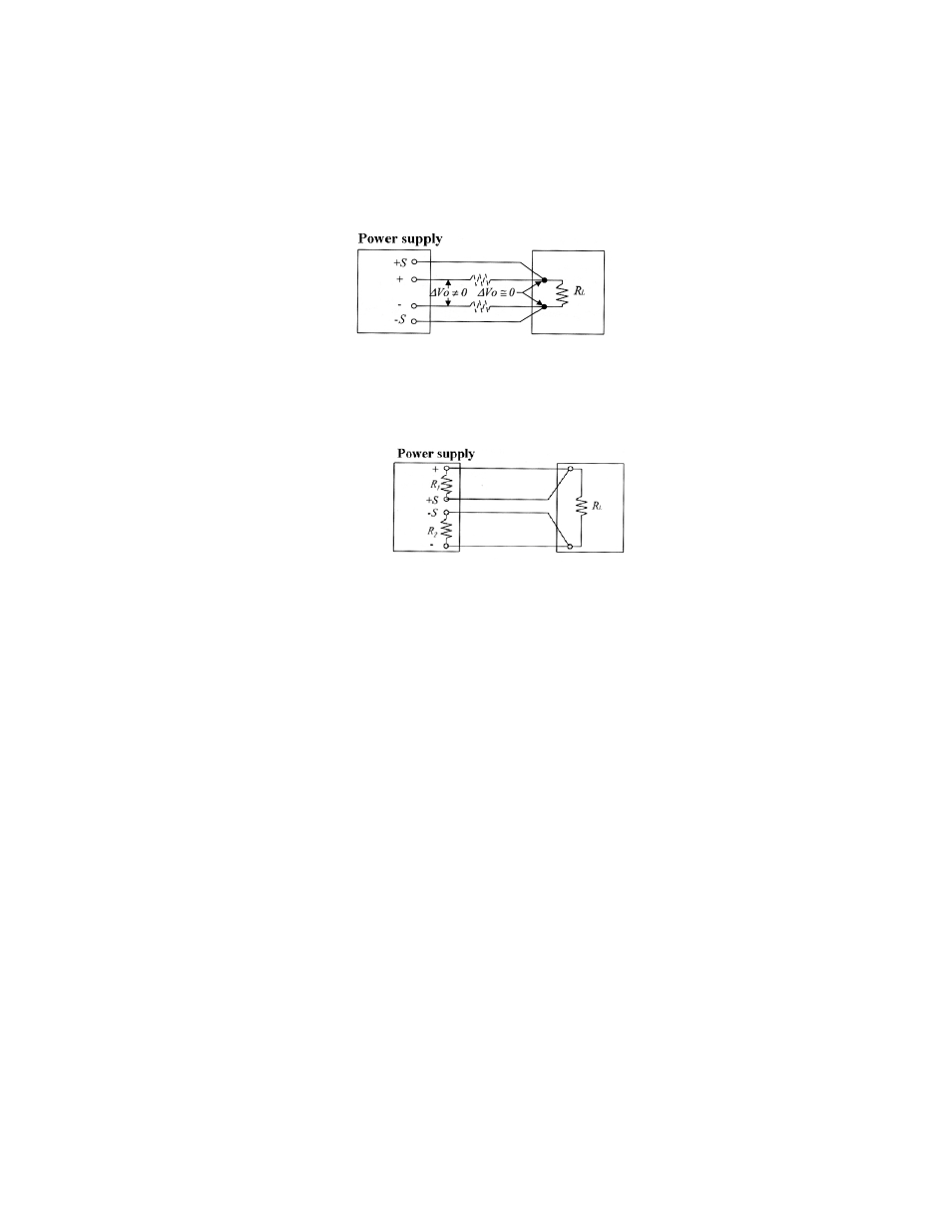
The function of the Remote Error Sensing can only be applied to the Constant Voltage mode as shown in Figure 6-3. The
feedback point of power supply must start from the load terminal directly. Therefore, the power supply can display its
function on the load terminal instead of output terminal. To compensate the voltage drop causing from the test lead, it
needs to shift the voltage from the output terminal of power supply, and the voltage on the load terminal remains
unchanged. A large test lead is recommended in order to reduce the voltage drop as less as better on the test lead (typical
0.5V maximum).
Never use the Sense connections without connecting the normal large test lead to output terminal.
Figure 6-3 The power supply with remote error sensing
Error Sensing Open Protection
The sensing circuit must avoid open circuit without equipping with Relay, Switch, and Connector. When the open circuit
is occurred abruptly on the sensing circuit, it will cause overshoot on the output terminal. To prevent this kind of
phenomenon, add small resistance R1 and R2 or replace with diode as shown in the Figure 6-4.
Figure 6-4 The power supply with remote error sensing protection