GW Instek GRF-3300 Series Student Manual User Manual
Page 7
16 Microstrip Line Filters
3
315
L
O
in
Z
Z
Z
2
(16-19)
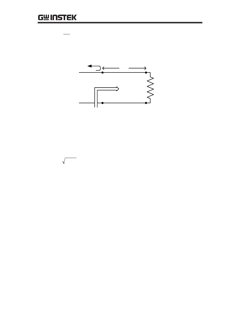
Referring to 16-19 and redrawing Figure 16-3 as Figure 16-4, we get:
L
R
in
Z
*
4
/
O
1
Z
0
Z
Figure 16-4
Z
L
is composed of a transmission line of characteristic impedance Z
l
and R
L
. In
order for
* to become 0, we also need Zin=Zo. The 16-13 shows the characteristic
impedance as:
L
O
l
R
Z
Z
(16-20)
Which is called Quarter-wave matching transformer.
16-1-5. Simulation Tools
The current simulation software tools are very useful for the designers, since they
can save lot of time for complicated calculations. Many tools are available meeting a
variety of demands. AppCAD developed by Agient (HP) is one of the tools for
calculating transmission line parameters, and it can be downloaded from the public
domain. The other software, like ADS and Momentum (by Agilent), MW Office (by
AWR), HFSS and Symphony (by Ansoft) etc., can simulate the design of a circuit so that
the designer can calculate the ideal results rapidly. Using the “Optimization” function in
the software, the circuit design can be automatically tuned to meet the target
specifications.
16-1-6. Suggestions and Reference of Microstrip Line Filters
The suggested steps of implementing microstrip line filters are as follows.