Lp: 1.6 [8 mm, for sma connector pin – GW Instek GRF-3300 Series Student Manual User Manual
Page 12
GRF-3300
Manual
3
320
x
Lp: 1.6
[8 mm, for SMA connector pin.
p
L
o
L
o
L
1
L
2
L
3
L
4
L
5
L
6
L
7
L
o
L
o
L
p
L
Figure 16-6
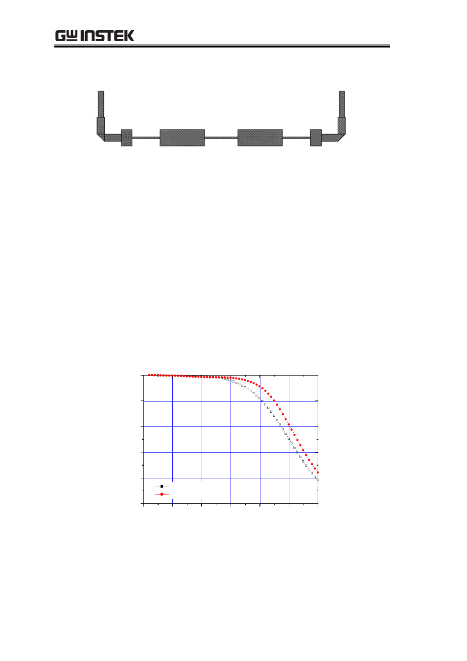
16-2-3. Fine tune and Modification
Just as mentioned in the previous section, the simulation tool is very useful and
important for microwave circuit design. We can simulate our design to check if the result
meets our design target. If not, we can do fine tuning and simulate again. By repeating this
fine tune and simulate step, we can make the design as close as possible to the design
target. In the above case, we find that the roll-off at fc=2GHz is 5dB more than we
expected from the simulation result. It could be caused by the extra sections of the
transmission line. Here we try to fine tune again by changing the
L
4
from 13.5mm to
10mm where the roll-off becomes 2.5dB but the attenuation at 3GHz becomes less than
20dB, which is a trade-off. Both simulation results are drawn in Figure 16-7.
0.0
0.5
1.0
1.5
2.0
2.5
3.0
-25
-20
-15
-10
-5
0
Stepped LPF
Insertion Loss (dB)
Frequency (GHz)
line4 = 13.5mm
line4 = 10mm
Figure 16-7
In the experiment, we will take the 10mm case for measurement.