GW Instek GRF-3300 Series Student Manual User Manual
Page 5
16 Microstrip Line Filters
3
313
16-1-2. Lossless Line
The above solution is intended for general transmission line including loss effects,
where the propagation constant and characteristic impedance are complex. However in
many practical cases, the loss of the line is very small and can be neglected, allowing
simplification of the above results. Setting R=G=0 in (16-3) gives the propagation
constant as:
LC
j
j
Z
E
D
J
(16-9)
LC
Z
E
(16-10)
0
D
(16-11)
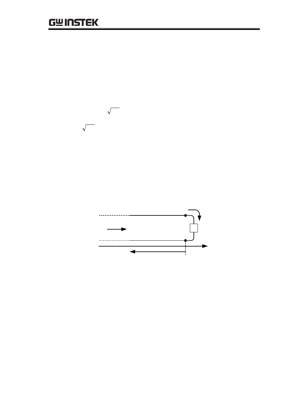
16-1-3. Terminated Lossless Transmission Line
Figure 16-3 shows a lossless transmission line terminated by an arbitrary load
impedance Z
L
. This diagram illustrates the wave refection problem in transmission lines,
a fundamental property of distributed systems.
)
(
),
(
z
I
z
V
L
V
E
,
O
Z
L
Z
L
I
z
0
in
Z
Figure 16-3
Assuming that a wave in the form V
0
+
e
- Mȕz
is generated from a source at
Z
< 0, we
can see that the ratio of voltage to current for such traveling wave is Z
0
, the characteristic
impedance. But when the line is terminated in an arbitrary load Z
L
=
0,
the ratio of voltage
to current at the load must be Z
L.
Thus, to satisfy this condition, a reflected wave must be
excited with the appropriate amplitude.
The amplitude of the reflected voltage wave normalized to the amplitude of the
incident voltage wave is known as the voltage reflection coefficient
*, expressed as: