Figure 10 alarm relay connections, Figure 11 typical 24vdc input connections, Figure 12 typical input power connections – Detcon 880S-N4X User Manual
Page 13
880-N4X
880-N4X Instruction Manual
Rev. 0.0
Page 9 of 36
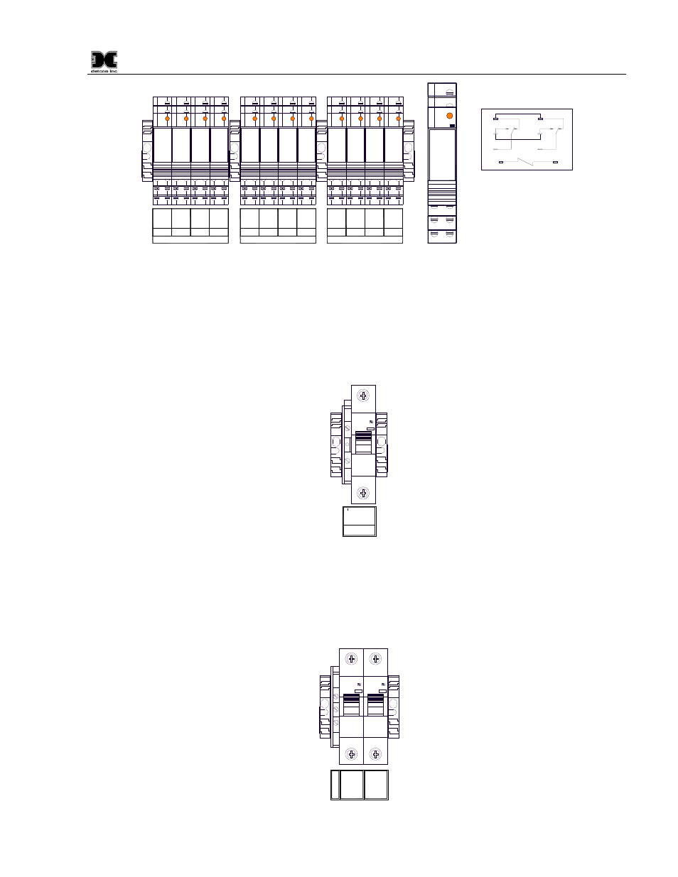
14-NO
FLT
11-NC
12-COM
14-NO
BANK 1
ALM1
11-NC
12-COM
14-NO
ALM2
11-NC
12-COM
14-NO
ALM3
11-NC
12-COM
14-NO
FLT
11-NC
12-COM
14-NO
BANK 2
ALM1
11-NC
12-COM
14-NO
ALM2
11-NC
12-COM
14-NO
ALM3
11-NC
12-COM
14-NO
FLT
11-NC
12-COM
14-NO
BANK 3
ALM1
11-NC
12-COM
14-NO
ALM2
11-NC
12-COM
14-NO
ALM3
11-NC
12-COM
11
14
12
11
14
12
NC - Normally Closed
NO - Normally Open
COM - Common
11
11
14
14
12
12
A2 (-)
A1 (+)
A1+
A2-
24
V
Figure 10 Alarm Relay Connections
5. If applicable, connect a 24VDC Battery Backup or Auxiliary 24V source to the terminal blocks
labeled “24VDC INPUT” (24V+ and 24V–) (Figure 11).
NOTE: This input should be capable of supplying at least 7 Amps at 24VDC in order for the unit to
operate properly. Insufficient current capabilities may cause detrimental damage to the unit and will
void the warranty.
24
V +
24
V -
24VDC
INPUT
I ON
C10
WMS1C10
240V-
10000
Figure 11 Typical 24VDC Input Connections
6. Connect 110-220VAC input to the Fuse Block labeled “VAC (L1)” in the lower left of the enclosure.
Connect Neutral (or L2) to terminal labeled “NEU (L2)” and Ground to the Green/Yellow terminal
labeled “GROUND” (Figure 12). The power supply is able to accept AC input voltages from 100 to
240 volts at 50 or 60Hz.
I ON
C3
WMS1C03
240V-
10000
I ON
C3
WMS1C03
240V-
10000
1
2
3
Gr
ou
nd
VAC (L
1)
NEU (L
2
)
Figure 12 Typical Input Power connections