0 installation, Installation, Figure 3 unit mounting and dimensional – Detcon 6400-N4X User Manual
Page 7
1600/6400-N4X
1600/6400-N4X- Instruction Manual
Rev. 1.1
Page 3 of 38
Programming Configuration
The 1600/6400 controllers are normally configured at Detcon based on application specific information
provided by the customer on the Configuration Form (See Section 13.0). It must be verified that the correct
quantity and type of I/O modules have been purchased to support the customer’s configuration requirements.
On the Configuration Form, the customer should supply all site-specific information pertaining to:
1) Number of gas channels
2) Range, units and gas type for each channel
3) Alarm level(s) for each gas channel
4) Tag Name for each channel
5) Assignment and set-up information for each relay contact
NOTE: The set-up configuration is fully field-programmable and can easily be executed by the user in the
field by following the instructions within this Operators Manual. Modifications to the set-up configuration are
expected to take place at the customers site due to requirement changes and/or system expansions.
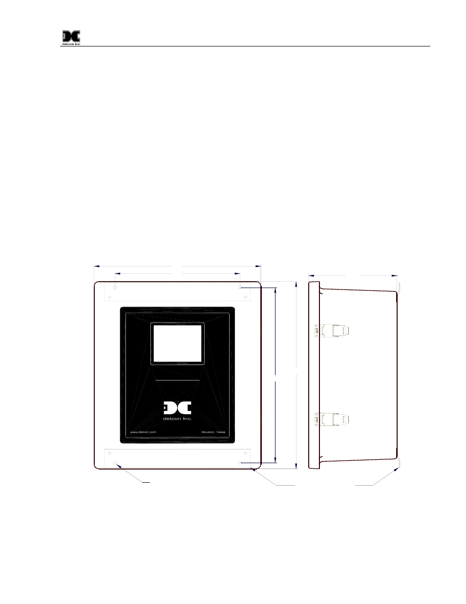
3.0 Installation
Securely mount the Model 1600/6400-N4X enclosure. Provide for suitable conduit/cable entry on the bottom
of the enclosure. Keep AC power separate from DC signals in conduit connections.
Muiti-Channel Gas Detection Control System
16.75"
17.87"
12"
16"
8.45"
Mounting Bracket
0.31 Dia. Mounting Holes (4ea.)
Model 6400-N4X
Figure 3 Unit Mounting and Dimensional
Connect 110/220VAC input wiring to the terminals labeled “VAC (L1)”, “Neutral (L2)”, and “Ground” (See
Figure 5). The Power Supply is capable of handling AC inputs from 110~240VAC 50-60Hz with no
degradation.
If applicable, connect 24 VDC to the terminals labeled “24VDC” and “DC Comm”, in Figure 5. This input
can be used for primary power or battery back-up power in the event of an AC power failure.