Figure 17 addressing da modules, Figure 18 addressing gas channels – Detcon 6400-N4X User Manual
Page 17
1600/6400-N4X
1600/6400-N4X- Instruction Manual
Rev. 1.1
Page 13 of 38
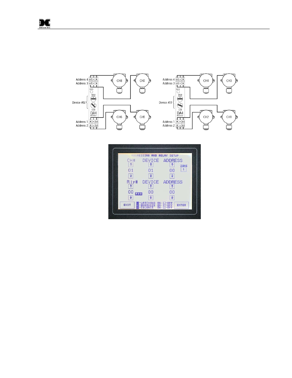
Use the up, down arrows to increment and decrement the entries. Press ‘ENTER’ after each new CH # entry is
made. The ‘Zone’ key increases in number as the ‘Zone’ key is pressed. When the maximum zone number is
reached, the ‘Zone’ key will start back at zone one and continue to advance with every key press. Do not wait
until all entries are made before hitting the ‘ENTER’ key to accept the inputs. It is best to enter a sensor and
enter the data before going on to the next sensor.
Figure 17 Addressing DA Modules
Figure 18 Addressing Gas Channels
Example: In this example, the 1600/6400 is to be set up for four I/O Modules. Two Model DA4 input
modules and two RL4 relay output modules. Make sure that the switch settings for the first Model DA4
module is set to 01. Set Channel # to 01, representing the first gas input and is wired to terminal connection
#1. Set the Device to 01, this represents the Model DA4 module with switch setting 01. Then set the Address
to 01, for position 1 on the module’s wiring connector. Press the ‘ENTER’ key to save the entry. For the
second gas channel, enter Channel # 02, keep the Device setting at 01 (since it is still using Device 01), and
enter Address 02. Press the ‘ENTER’ key to save the entry. Continue this sequence for the third and fourth
gas channels. In a matrix table, the first two Model DA4 modules would look like this:
CH #
Device
Address
01
01
01
02
01
02
03
01
03
04
01
04
The second Model DA4 module with identification switches set to 02 and handling sensor inputs 5 – 8, would
appear as follows:
CH #
Device
Address
05
02
01