1 installing the i/o modules, 2 connecting to the i/o modules, Installing the i/o modules – Detcon 6400-N4X User Manual
Page 10: Connecting to the i/o modules, Figure 6 i/o module installation, Figure 7 model da-4 and 4-20ma gas sensors
1600/6400-N4X
1600/6400-N4X- Instruction Manual
Rev. 1.1
Page 6 of 38
3.1 Installing the I/O Modules
Normally, the I/O modules will be factory installed on the main NEMA 4 rack and ready for wiring to external
devices (sensors and alarm annunciators). If they are not installed, follow the procedure below.
I/O modules are mounted to industry-standard 37.5 x 7.5 mm din-rail. Install the first I/O module on the din
rail and slide it all the way to the right side stop. When installing additional I/O modules, make sure there is
about 0.5 inch clearance spacing on either side of the module and snap onto the din rail (the 0.5” spacing is to
allow for connector clearance). Once the I/O module is snapped onto the din-rail, slide it to the right and
assure that it firmly plugs into the next module. Repeat as necessary for the balance of the modules. The
Controller Enclosure has room for a maximum of eight I/O modules. Additional modules should be mounted
in a separate enclosure.
DA
4
4
-20
m
A
Mo
du
le
RL
4 Re
la
y
M
od
ul
e
RL
4 Re
la
y
M
od
ul
e
RL
4 Re
la
y
M
od
ul
e
RL
4 Re
la
y
M
od
ul
e
A
DA
4
4
-20
m
A
Mo
du
le
DA
4
4
-20
m
A
Mo
du
le
DA
4
4
-20
m
A
Mo
du
le
Use Belden PN 9841
RS-485 Cable
I/O Connector
Detcon P/N 306-189320-300
B
S
+
-
RS-485 and power Cable
Use Belden PN 1502P
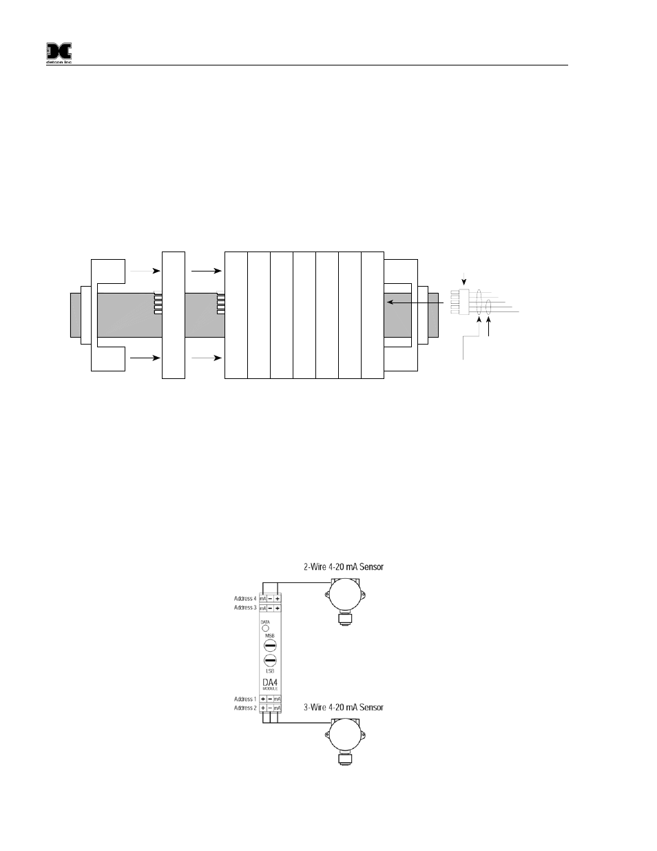
Figure 6 I/O Module Installation
For addressable I/O modules or Modbus™ sensors that are being located remotely from the 1600/6400
controller use Belden 1502P cable for serial and power connections. For serial only connections use Belden
9841 cable. Interconnection is accomplished using the din-rail terminal blocks shown in Figure 5.
3.2 Connecting to the I/O Modules
4-20mA Gas Sensors
Connect 4-20mA type gas sensors to the Model DA4 4-20mA input modules. There are four 4-20mA inputs
in each Model DA4 module.
Figure 7 Model DA-4 and 4-20mA Gas Sensors