Figure 33 correct and incorrect wiring schemes – Detcon 6400-N4X User Manual
Page 34
1600/6400-N4X
1600/6400-N4X- Instruction Manual
Rev. 1.1
Page 30 of 38
The characteristic impedance of the cable must be between 100 to 120 ohms. Twisted pair is used because if
the cable does run near a noise source both conductors will pick up the same amount of noise, therefore
effectively canceling it out.
Incorrect Wiring Schemes
Some of the biggest problems with an RS-485 bus are the use of incorrect wiring schemes mixed with
improper or no line termination.
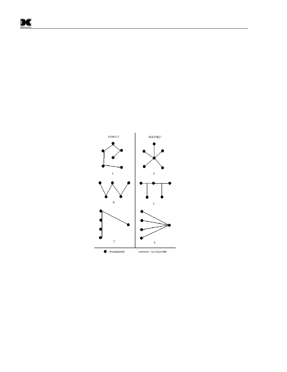
Most installations are not used to having to run wires in a daisy-chain fashion, instead wire runs tend to
originate from a central point and run to different devices in a star-like pattern. This is the absolute worst way
to wire an RS-485 bus. The chances of problem free operation over the life of the equipment decreases
dramatically the further you stray from a straight daisy-chain wiring scheme. The bus needs to be terminated
at each end of the cable run to operate ideally. Other wiring schemes introduce multiple “cable ends” making
it impossible to balance the lines. Wiring as in Figure 33 (A, B & C) would more than likely require no
special fixes to provide reliable data flow. (D, E & F) could possibly be made to operate, but would require
many repeaters and man-hours to do so.
Figure 33 Correct and incorrect wiring schemes
Grounding
Another problem that can occur with RS-485 is incorrect grounding. Neither one of the two conductors in the
cable is ground. Both of the conductors are supplying a current to maintain a voltage level relative to an
external reference. A third conductor must be supplied to establish a reference through earth ground.
RS-485 is specified to be able to work normally with a ±7V ground potential difference and survive ±25V
surges. In most applications, the equipment is powered from its own DC power supplies. This is good as long
as the supplies are located in the same physical location, and the DC commons are tied together and tied to
earth ground.
Problems occur when part of the data bus is powered by one supply and the second part of the bus is powered
by a power supply located elsewhere. In this case, earth ground is being relied upon to be the reference
between the two sections of the bus. If noise is induced onto the earth ground of one power supply and not the